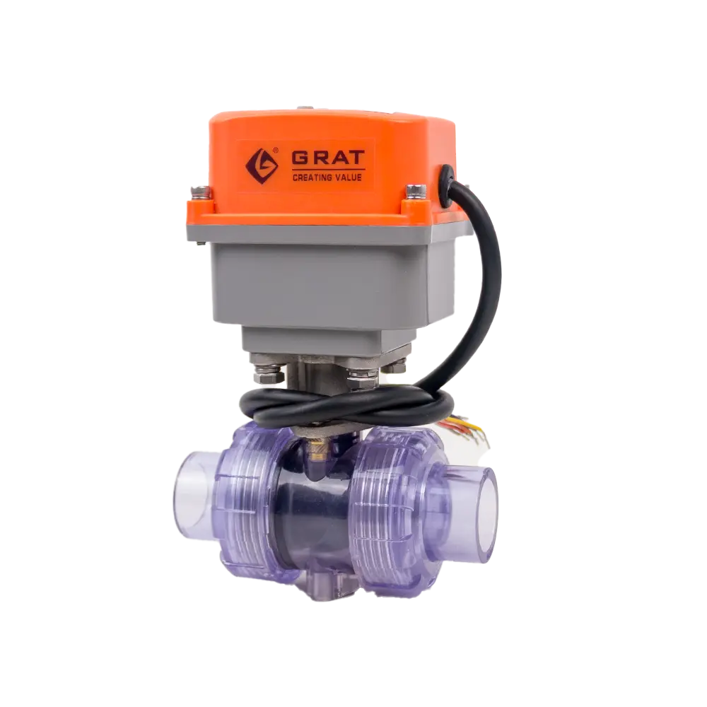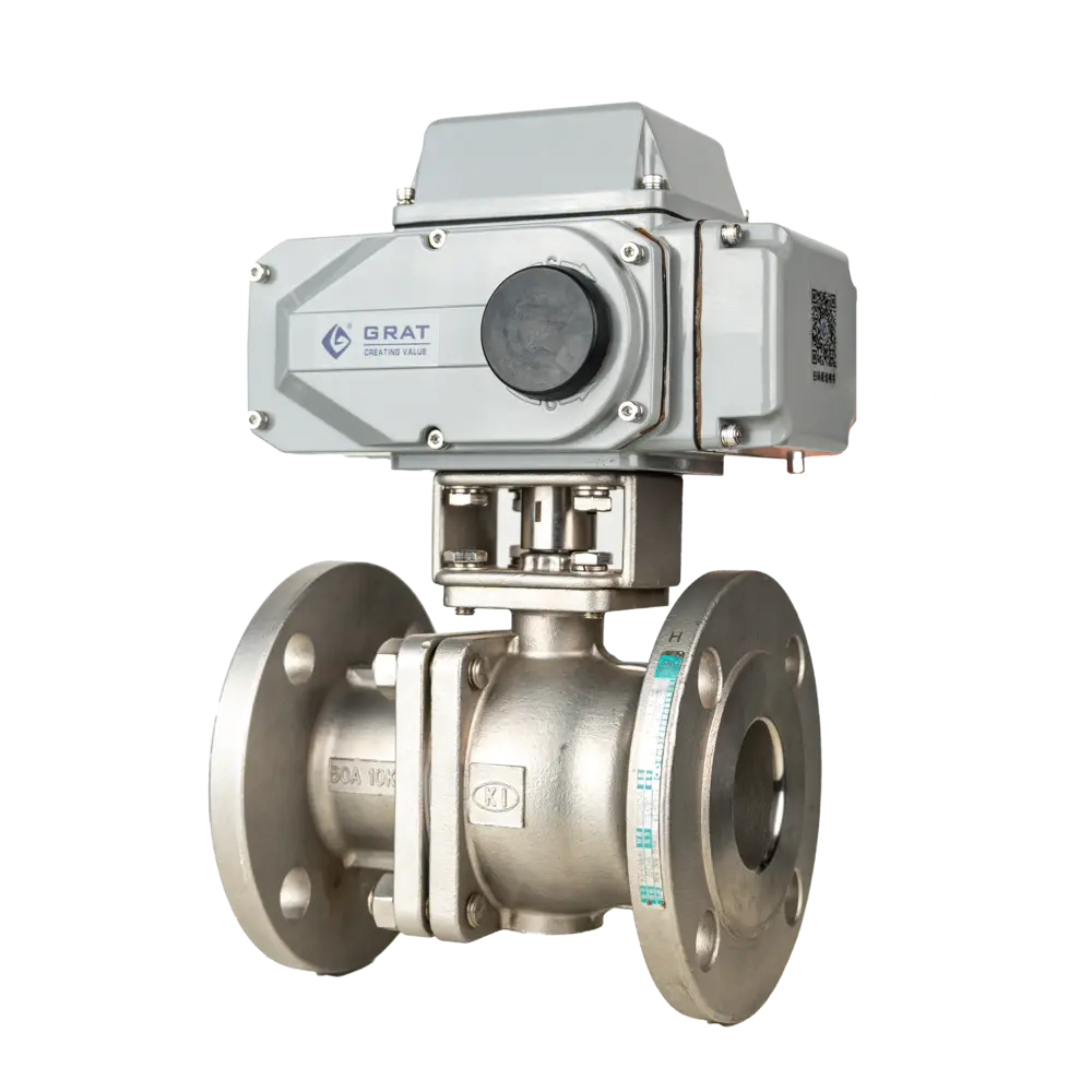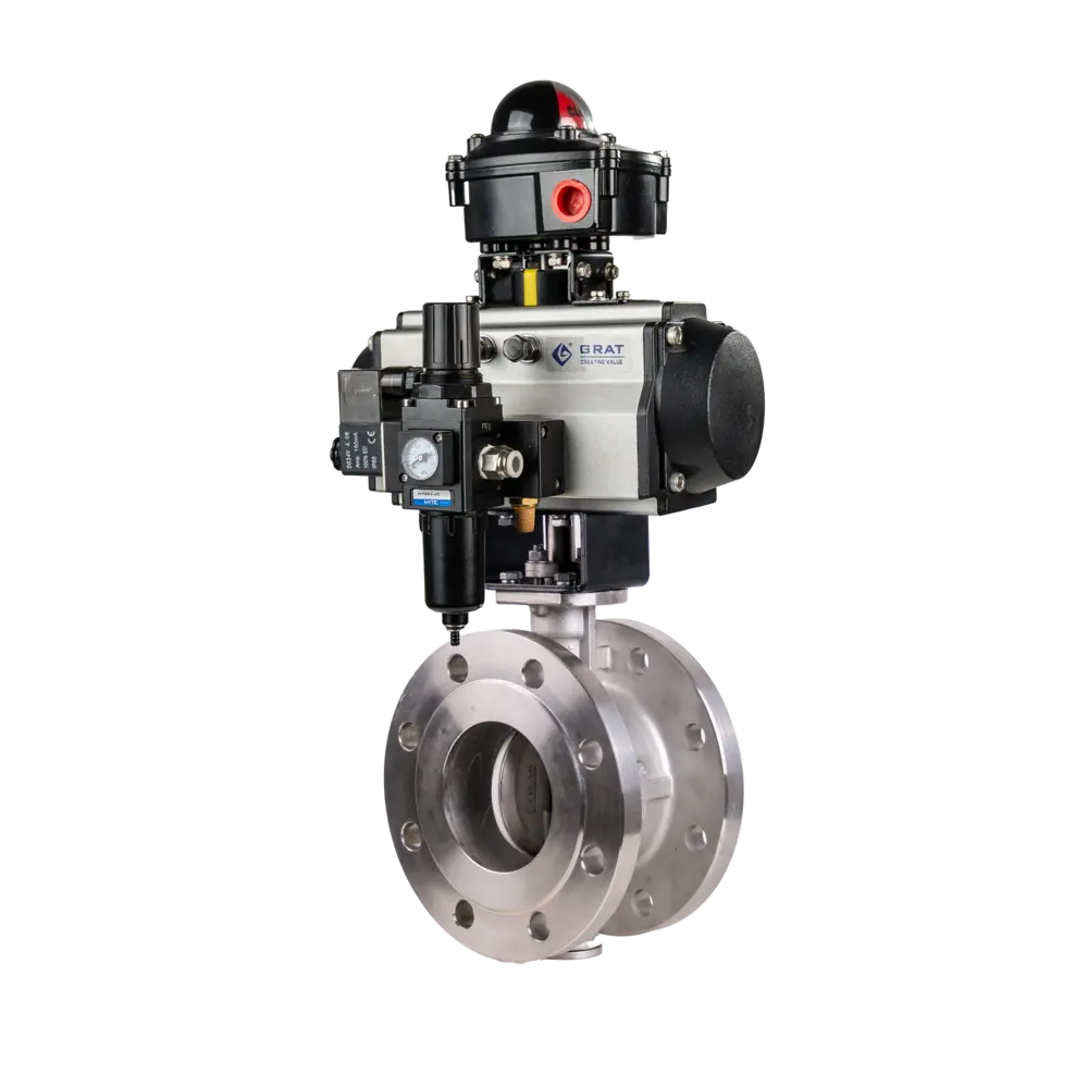

Electric Ultra-Short Flanged Ball Valve
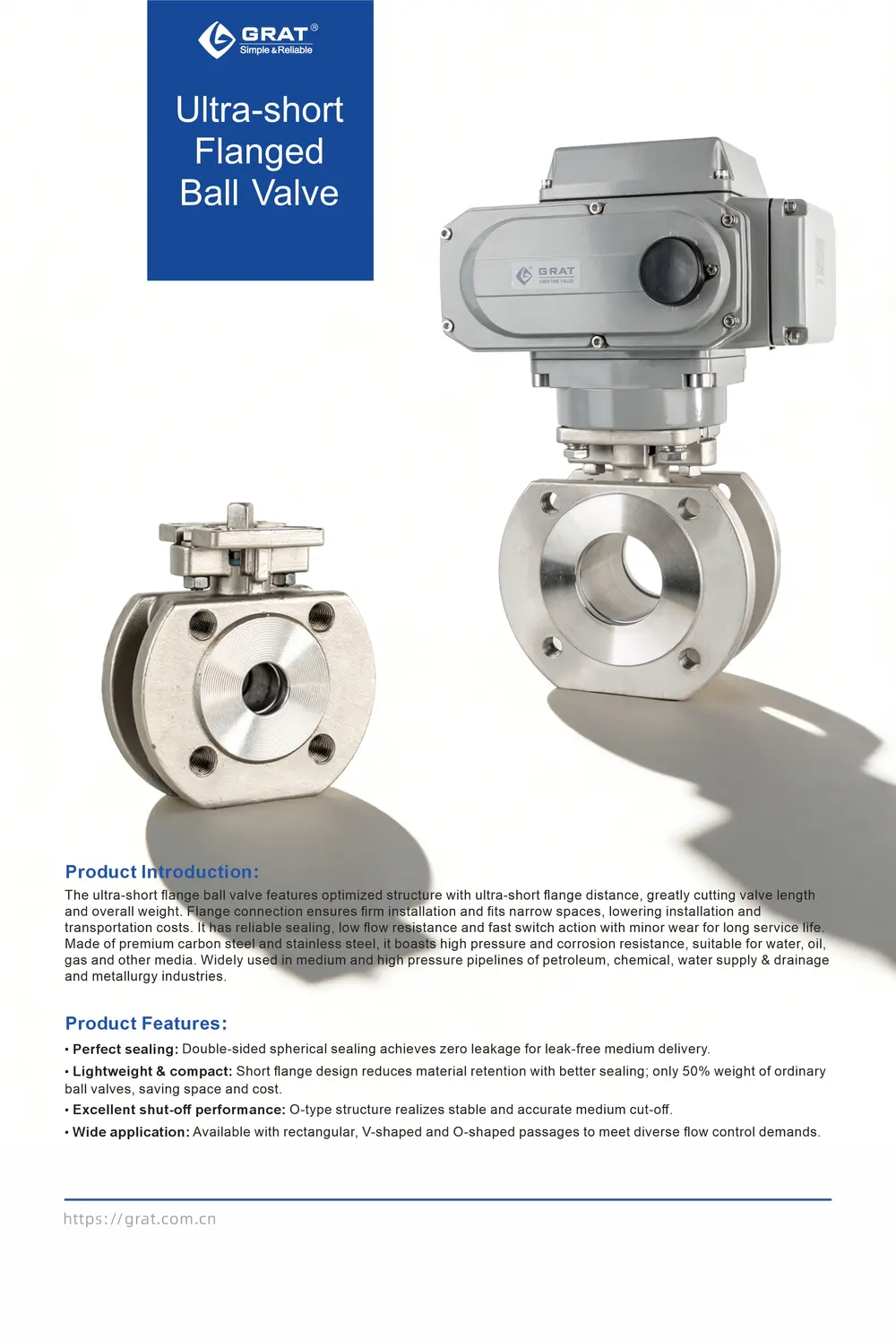
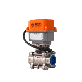
The Ultra-Short Flanged Electric Ball Valve is a compact, electrically actuated valve designed for space-constrained installations, featuring a significantly reduced flange-to-flange length, stainless steel construction for superior corrosion resistance and zero leakage in high-pressure/temperature applications across chemical, petroleum, and industrial systems.
Tags
Features
Double-sided spherical sealing function, meeting zero-leakage standards.
O-type on-off ball valves offer excellent shut-off performance.
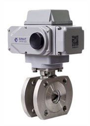
Ultra-short flange distance structure: the valve seat is positioned close to the end flange, minimizing material retention and delivering superior sealing performance. Compared with conventional electric ball valves, its weight is significantly reduced to approximately 50%, and it features a compact structure and small size.
Ball core channel shapes are available in rectangular, V-shaped, and O-shaped options.
- It features compact structure, small size, light weight and easy installation.
- It is mainly used to cut off or connect the medium in the pipeline, and can also be applied to the regulation and control of fluids.
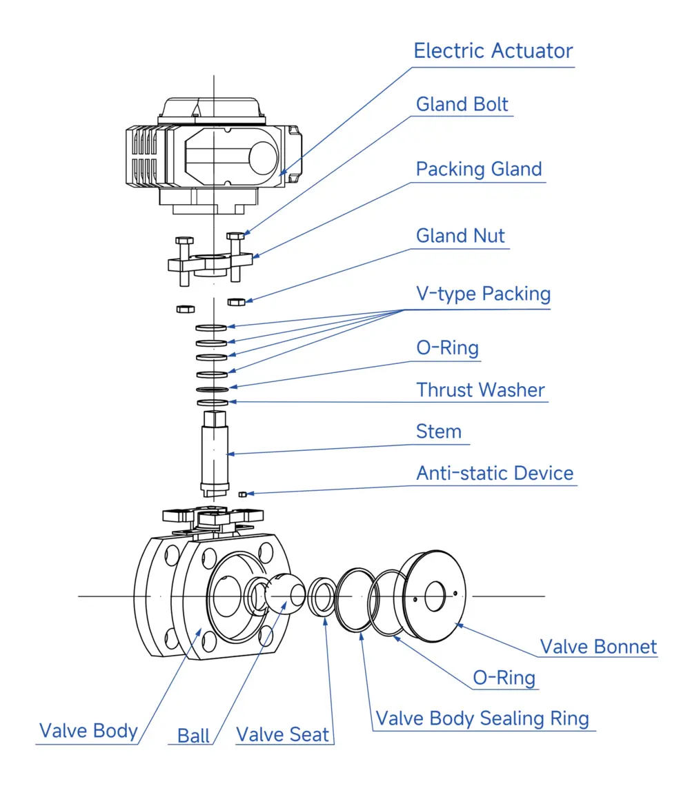
- The valve seat is equipped with sealing rings made of elastic materials such as PTFE. Thanks to the excellent self-lubricating property of PTFE and similar materials, the friction loss with the ball is small, effectively prolonging the service life of the product.
- The stem seal is reliable. Since the stem only rotates without lifting movement, the packing seal of the stem is not easily damaged, and the sealing capacity increases with the rise of medium pressure.
- The bottom-mounted stem is designed with a protruding step to prevent the stem from blowing out. In case of fire damage to the stem seal, metal-to-metal contact between the step and the stem can still be formed to ensure stem sealing.
- It is widely used in petroleum, chemical, metallurgical, power station, light industry and other fields for automatic regulation or on-off control of oil, water, gas, pulp and fibrous fluids.
- Anti-static function: Springs are installed between the ball, stem and valve body to discharge static electricity generated during the opening and closing process.
Basic Parameters
Material Specifications
Body & Internal Components
Standards & Specifications
Suitable Media
- Water
- Petroleum
- Nitric Acid Series
- Acetic Acid Series
- Viscous Fluid
- Strong Oxidizing Medium
Standards Compliance
Main Parameters
| Item | Specification |
|---|---|
| Operating Power Supply | AC110V, AC220V, AC380V, DC24V |
| Nominal Diameter | DN15 - 200 |
| Medium Temperature | -20℃ to +350℃ (+200℃ for special sealing) |
| Working Pressure | PN16, PN25, PN40, PN64 |
| Control Mode | Regulating or On-Off Control |
| Connection Type | Flanged Type |
| Valve Body Material | WCB, SUS304, SUS316 |
| Valve Core Material | SUS304, SUS316 |
| Valve Seat Material | PTFE (normal temperature), Special PPL (high temperature) |
| Leakage Rate | Complies with ANSI B16.104 Class V Standard |
| Sealing Form | Elastic Sealing, High Temperature Resistant Para-Polyphenylene |
| Applicable Medium | Water, Petroleum, Nitric Acid Series, Acetic Acid Series, Viscous Fluids, Strong Oxidizing Media, etc. |
| Protection Class | IP67 |
| Design and Manufacturing Standards | GB12237-2021, API 6D |
| Flange Standards | JB/T 79-2015, GB/T 9124.1-2019, GB/T 9124.2-2019, ANSI B16.5, JIS B2239 |
| Structural Length | GB12221-2005 |
| Inspection Standard | API 598 |
Dimension Drawing
1.Outline Drawing and Connection Dimensions of Ultra-Short Flange Electric Ball Valve
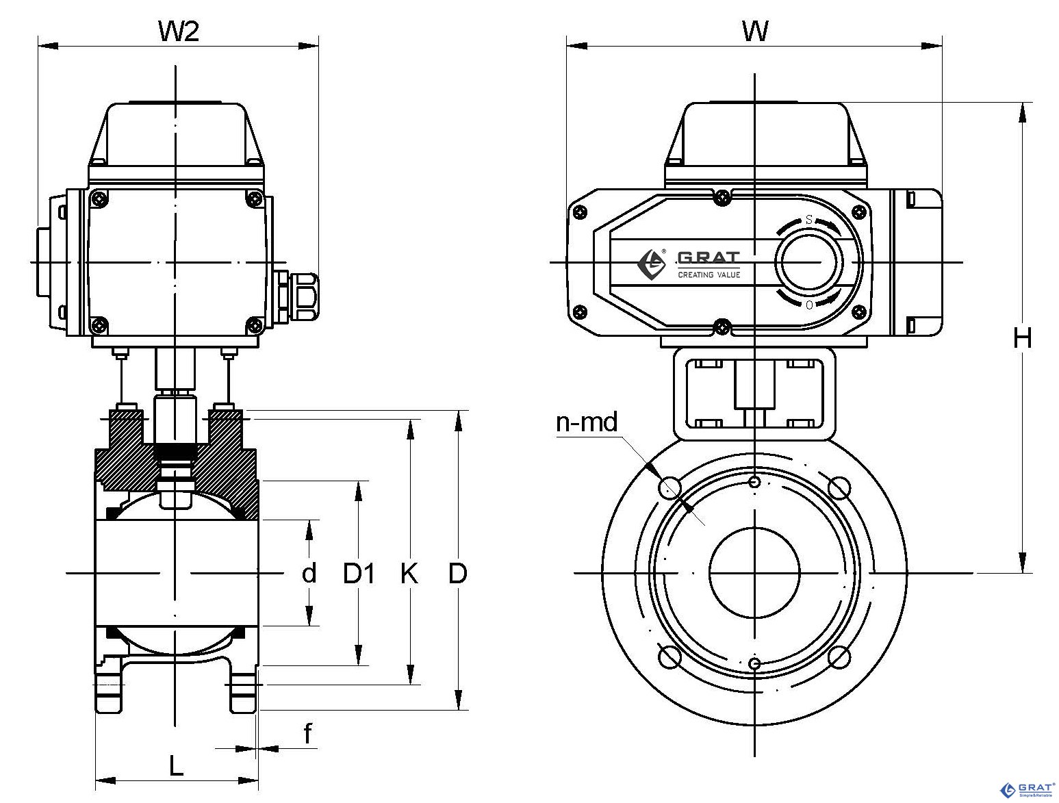
2.National Standard Installation Dimensions of Ultra-Short Flange Electric Ball Valve
Design Standard: GB/T 12237-2007
Flange Standard: GB/T 9113-2010 National Standard Unit: (mm)
| Nominal Diameter(DN) | d | D1 | K | D | n-Md | f | L | H | W1 | W2 | |
| mm | in | ||||||||||
| DN15 | 1/2〃 | 15 | 45 | 65 | 95 | 4-M12 | 2 | 35 | 210 | 196 | 145 |
| DN20 | 3/4〃 | 19 | 55 | 75 | 105 | 4-M12 | 2 | 38 | 216 | 196 | 145 |
| DN25 | 1〃 | 25 | 65 | 85 | 115 | 4-M12 | 2 | 50 | 223 | 196 | 145 |
| DN32 | 1 1/4〃 | 28 | 76 | 100 | 140 | 4-M12 | 2 | 50 | 230 | 196 | 145 |
| DN40 | 1 1/2〃 | 38 | 83 | 110 | 148 | 4-M16 | 3 | 67 | 240 | 196 | 145 |
| DN50 | 2〃 | 49 | 102 | 125 | 156 | 4-M16 | 3 | 72 | 250 | 196 | 145 |
| DN65 | 2 1/2〃 | 64 | 120 | 145 | 185 | 4-M16 | 3 | 94 | 298 | 255 | 182 |
| DN80 | 3〃 | 73 | 143 | 160 | 200 | 8-M16 | 3 | 120 | 312 | 255 | 182 |
| DN100 | 4〃 | 90 | 168 | 180 | 220 | 8-M16 | 3 | 141 | 322 | 255 | 182 |
| DN125 | 5〃 | 110 | 185 | 210 | 245 | 8-M16 | 3 | 165 | 397 | 255 | 182 |
| DN150 | 6〃 | 145 | 208 | 240 | 277 | 8-M20 | 3 | 225 | 422 | 255 | 182 |
| DN200 | 8〃 | 195 | 265 | 395 | 335 | 12-M20 | 3 | 275 | 512 | 255 | 182 |
3.DIN Standard Installation Dimensions of Ultra-Short Flange Electric Ball Valve
Design Standard: DIN 3375/1, 2, EN 12516-1
Flange Standard: DIN EN 1092-1 PN10–PN40 DIN Standard Unit: (mm)
| Nominal Diameter(DN) | d | D1 | K | D | n-Md | f | L | H | W1 | W2 | |
| mm | in | ||||||||||
| DN15 | 1/2〃 | 15 | 45 | 65 | 95 | 4-M12 | 2 | 44 | 220 | 196 | 145 |
| DN20 | 3/4〃 | 20 | 58 | 75 | 105 | 4-M12 | 2 | 44 | 220 | 196 | 145 |
| DN25 | 1〃 | 25 | 68 | 85 | 115 | 4-M12 | 2 | 50 | 223 | 196 | 145 |
| DN32 | 1 1/4〃 | 32 | 78 | 100 | 140 | 4-M16 | 2 | 60 | 237 | 196 | 145 |
| DN40 | 1 1/2〃 | 38 | 88 | 110 | 150 | 4-M16 | 3 | 65 | 244 | 196 | 145 |
| DN50 | 2〃 | 49 | 102 | 125 | 165 | 4-M16 | 3 | 80 | 245 | 196 | 145 |
| DN65 | 2 1/2〃 | 62 | 122 | 145 | 185 | 4-M16 | 3 | 110 | 306 | 255 | 182 |
| DN80 | 3〃 | 74 | 138 | 160 | 200 | 8-M16 | 3 | 120 | 326 | 255 | 182 |
| DN100 | 4〃 | 100 | 158 | 180 | 220 | 8-M16 | 3 | 152 | 338 | 255 | 182 |
| DN125 | 5〃 | 118 | 188 | 210 | 250 | 8-M16 | 3 | 180 | 363 | 255 | 182 |
| DN150 | 6〃 | 150 | 212 | 240 | 285 | 8-M20 | 3 | 232 | 396.5 | 255 | 182 |
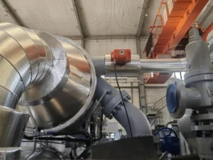
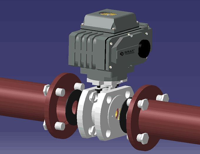
4.Installation Diagram of Ultra-Short Flange Electric Ball Valve and Pipeline
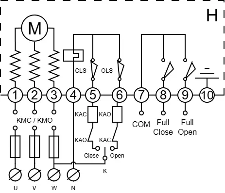
Circuit Diagram
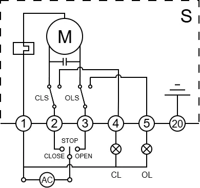
S
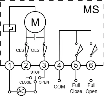
MS
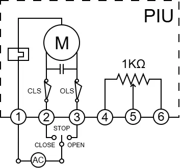
PIU
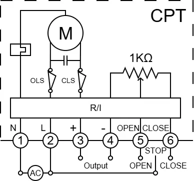
CPT
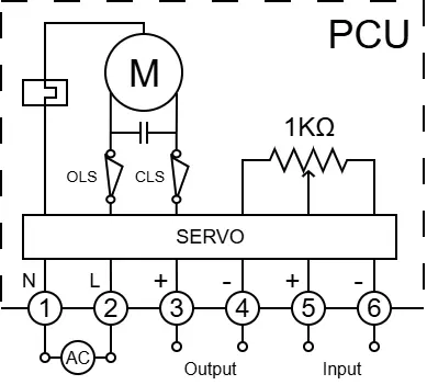
PCU
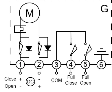
G
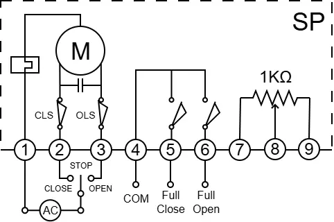
SP