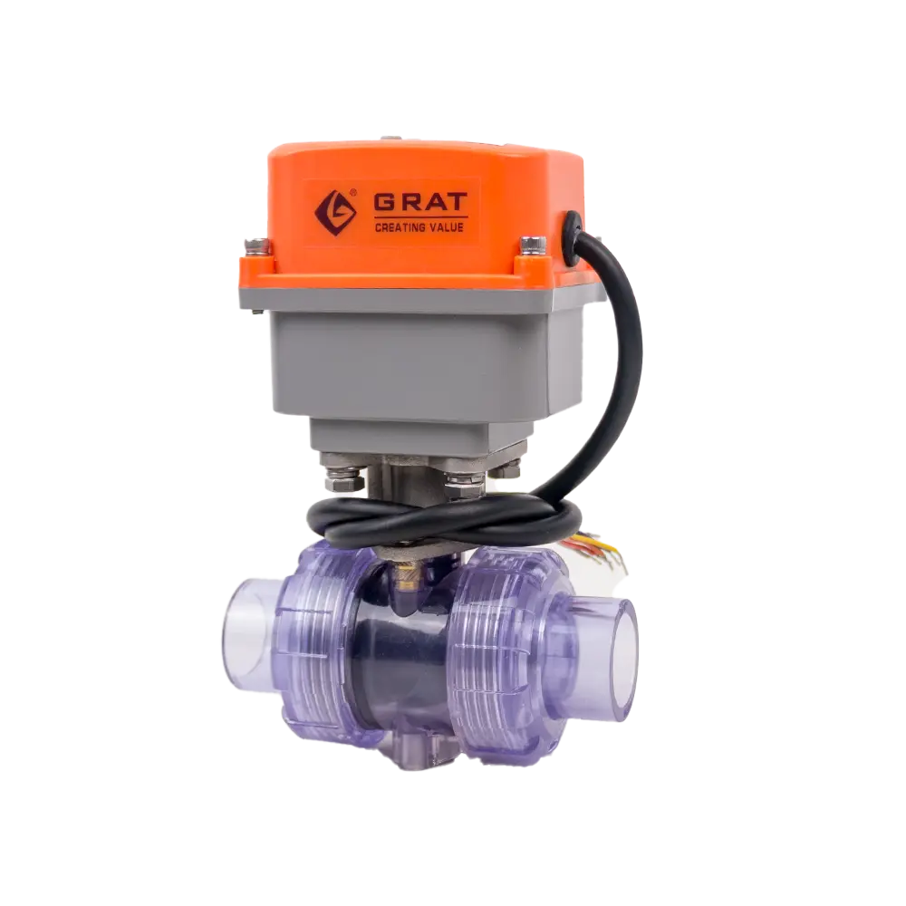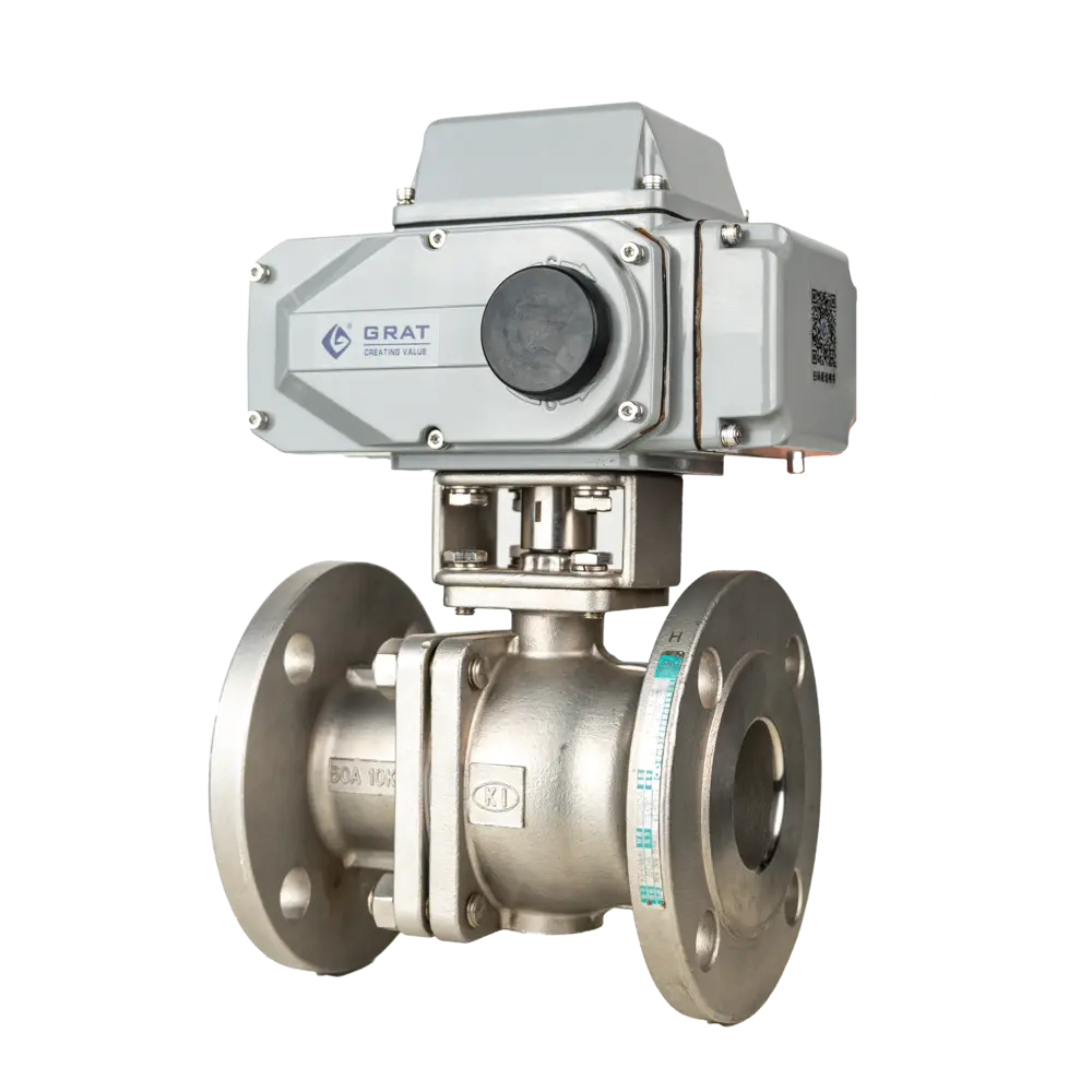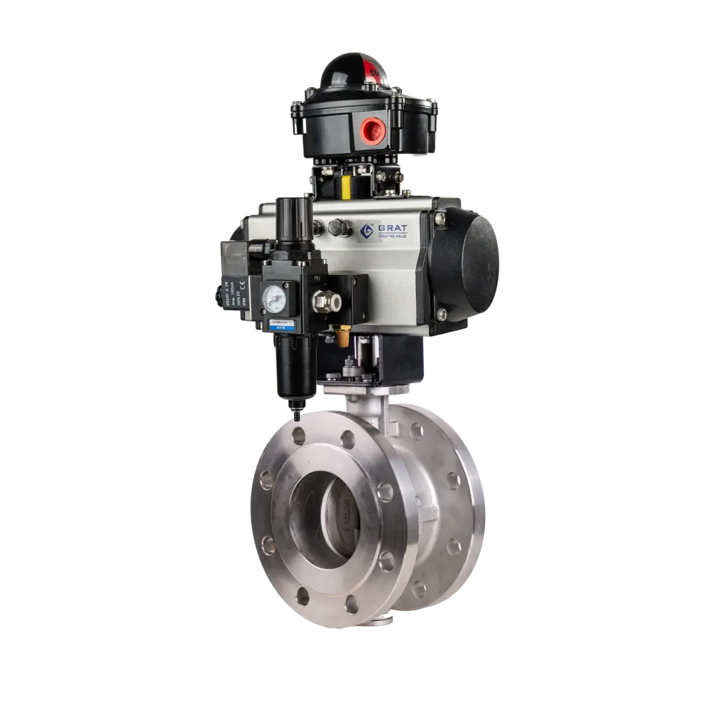
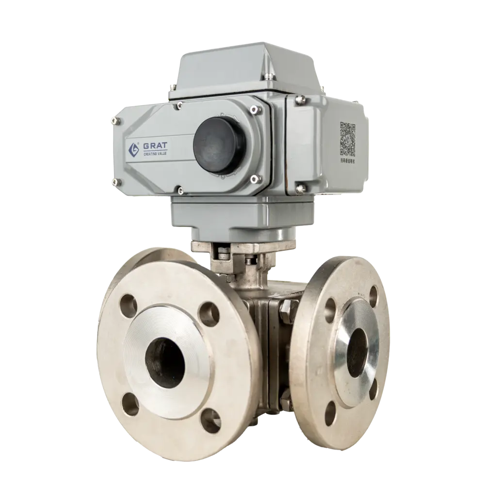
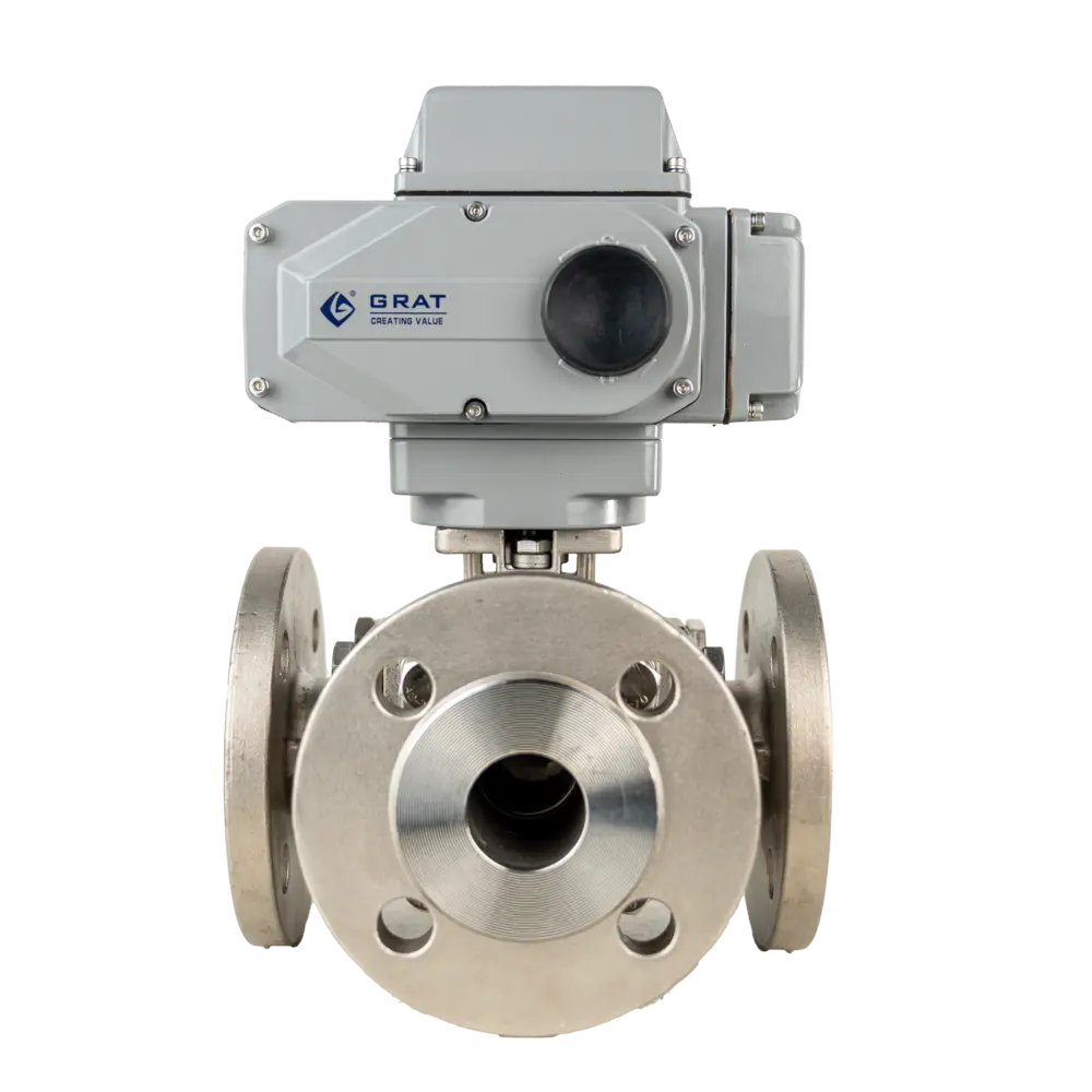
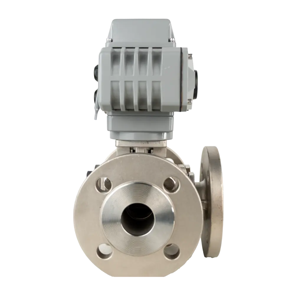
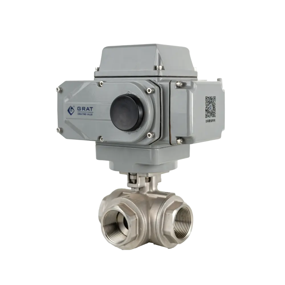
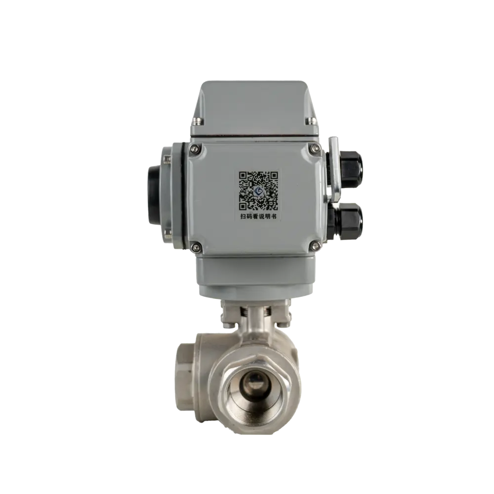
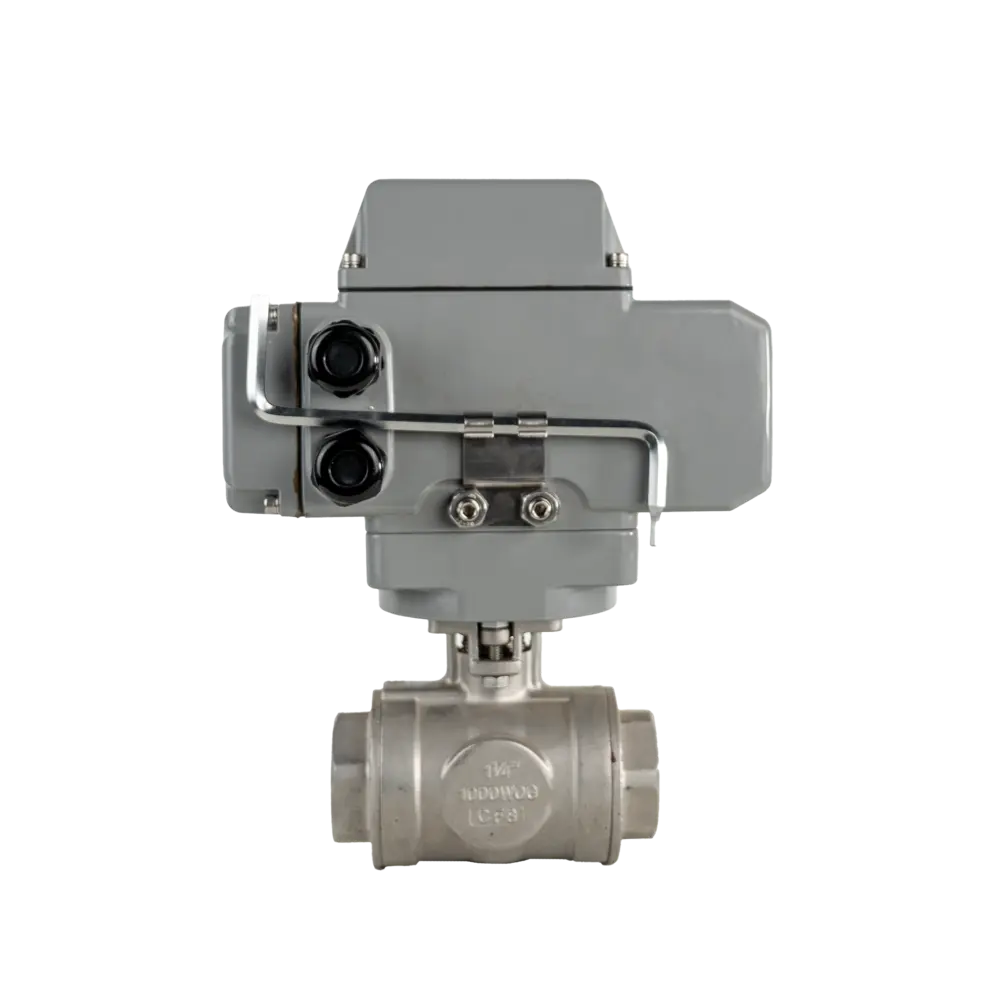

Electric Three Way Ball Valve
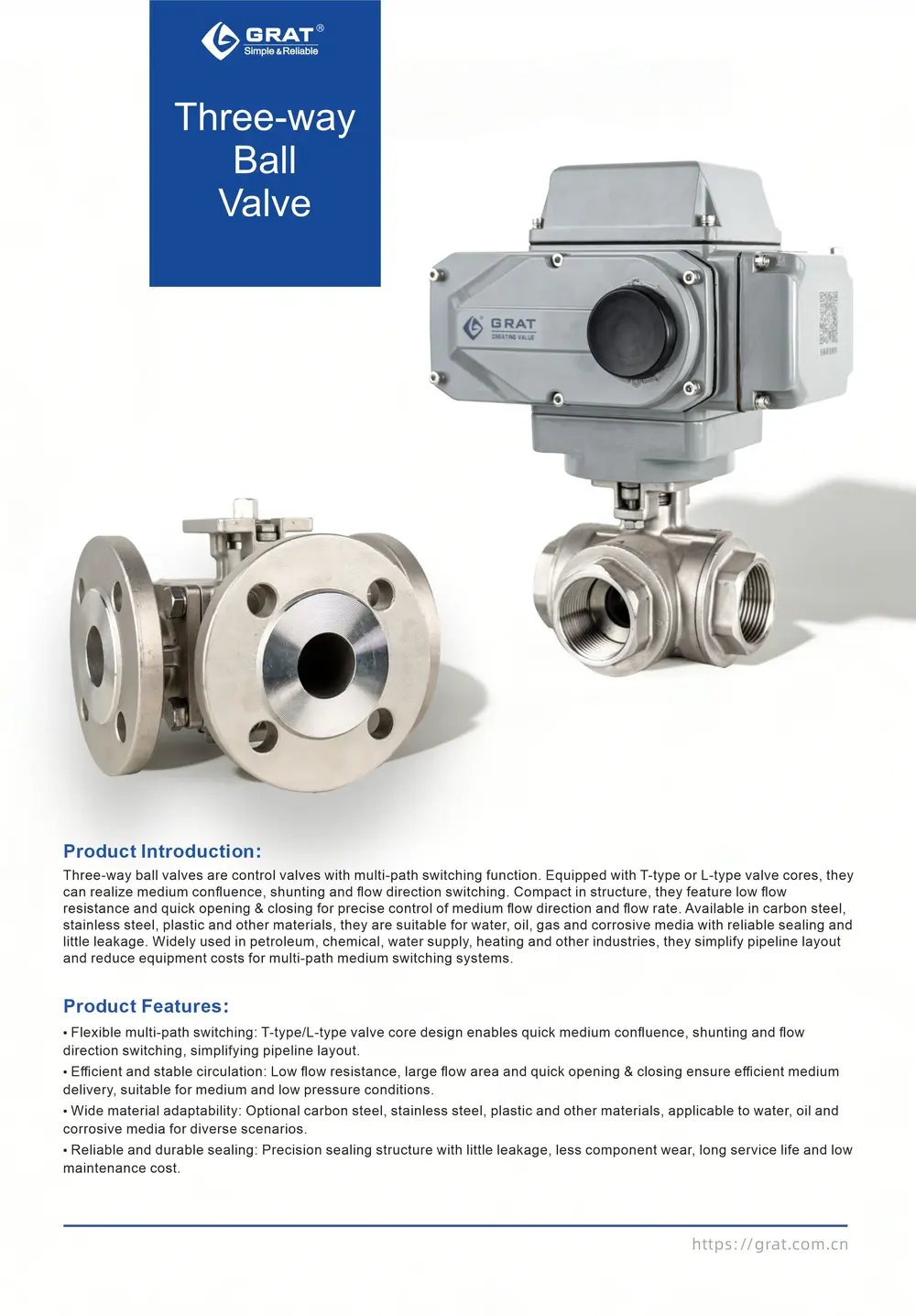
The Electric Three-Way Ball Valve, with sanitary connections and electric actuation, installs easily in hygienic systems and provides precise flow-direction control across three ports. Used in food, beverage, and pharmaceutical applications requiring strict sanitation.
Tags
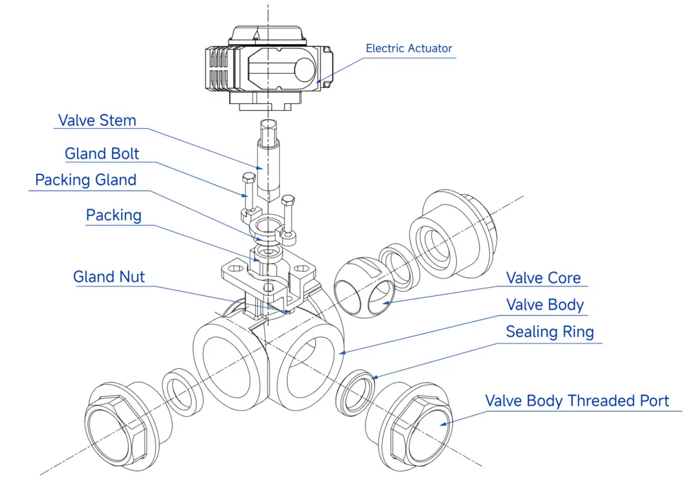
Features
Three-way ball valves divert or combine flow. These multi-port valves use two or four seats, and any port can serve as the zero-leakage inlet. Available in L-port or T-port, they handle diversion, mixing, reversing, and full flow through all three ports.
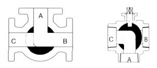
L-port: two seats for flow-path switching.
T-port: four seats for balanced forces and reliable sealing.
Basic Parameters
Material Specifications
Body & Internal Components
Standards & Specifications
Suitable Working Conditions
- Air Conditioning Systems
- Fire Protection Systems
- Water Treatment
- Pipeline Purging
- Analytical Instruments
- Flue Gas Sampling
Standards Compliance
Main Parameters
1.Installation Dimensions of IoT Mini Electric Flange Three-Way Ball Valve
| Nominal Diameter | DN15~100 |
| Power Supply | AC110V, AC220V, AC380V, DC24V |
| Actuator Torque / Material | Cast Aluminum Alloy |
| Medium Temperature | 0~120℃ |
| Ambient Temperature | -30℃-60℃ |
| Nominal Pressure | 0.1~6.4MPa |
| Control Mode | On-off Control |
| Actuation Time | 4-90 Seconds |
| Applicable Conditions | Air Conditioning, Fire Protection Systems, Water Treatment, Pipeline Purging, Analytical Instruments, Flue Gas Sampling, etc. |
| Connection Type | Female Thread, Flange |
| Sealing Type | Soft Seal |
| Valve Body Material | SUS304, SUS316, WCB |
| Valve Core Material | SUS304, SUS316 |
| Seal Ring Material | EPDM, PTFE |
| Protection Grade | IP67 |
| Installation Method | Installable at Any Angle (Horizontal or Inclined Installation Recommended for Longer Service Life) |
| Design and Manufacturing Standard | GB12237-2021, API 6D |
| Flange Standard | GB/T 9124.1-2019, GB/T 9124.2-2019, GB17241.6-2008 |
| Face-to-Face Dimension Standard | GB12221-2005 |
| Inspection Standard | API 598 |
Dimension Drawing
1.Installation Dimensions for Flanged Pneumatic Three-Way Ball Valve
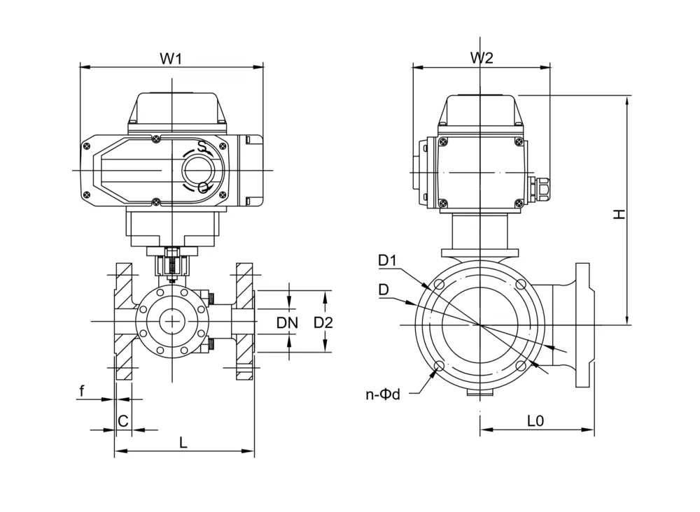
| Nominal Diameter (DN) | L | L0 | D2 | C | f | D | D1 | H | n-Φd | L1 | L2 |
| 15 | 150 | 75 | 45 | 14 | 2 | 95 | 65 | 216 | 4-Φ14 | 196 | 145 |
| 20 | 160 | 80 | 55 | 14 | 2 | 105 | 75 | 230 | 4-Φ14 | 196 | 145 |
| 25 | 180 | 90 | 65 | 14 | 2 | 115 | 85 | 236 | 4-Φ14 | 196 | 145 |
| 32 | 200 | 100 | 78 | 16 | 2 | 135 | 100 | 245 | 4-Φ18 | 196 | 145 |
| 40 | 220 | 110 | 85 | 16 | 3 | 145 | 110 | 258 | 4-Φ18 | 196 | 145 |
| 50 | 240 | 120 | 100 | 16 | 3 | 160 | 125 | 264 | 4-Φ18 | 196 | 145 |
| 65 | 260 | 130 | 120 | 16 | 3 | 180 | 145 | 302 | 4-Φ18 | 255 | 182 |
| 80 | 280 | 140 | 135 | 18 | 3 | 195 | 160 | 310 | 8-Φ18 | 255 | 182 |
| 100 | 320 | 160 | 155 | 20 | 3 | 215 | 180 | 320 | 8-Φ18 | 255 | 182 |
2.Installation Dimensions for Screwed Pneumatic Three-Way Ball Valve
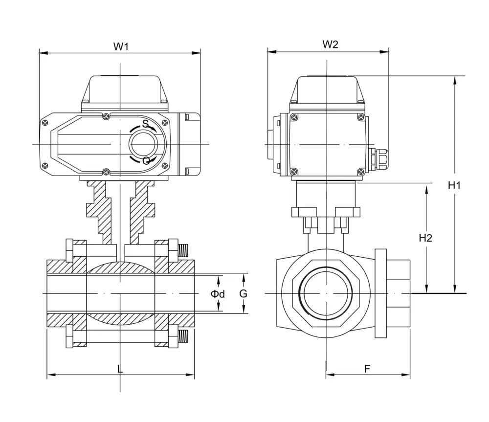
| Nominal Diameter (DN) | L | G | Φd | F | H1 | H2 | W1 | W2 |
| 12 | 70 | Thread Standard NPT BSP DIN etc | 12 | 40 | 196 | 38 | 196 | 145 |
| 15 | 83 | 15 | 42 | 198 | 40 | 196 | 145 | |
| 18 | 89 | 18 | 54 | 208 | 50 | 196 | 145 | |
| 25 | 116 | 25 | 60 | 217 | 59 | 196 | 145 | |
| 32 | 134 | 32 | 68 | 228 | 70 | 196 | 145 | |
| 38 | 152 | 38 | 84 | 232 | 74 | 196 | 145 | |
| 50 | 200 | 50 | 98 | 251 | 93 | 196 | 145 | |
| 65 | 240 | 65 | 106 | 302 | 110 | 255 | 182 | |
| 80 | 278 | 80 | 114 | 325 | 133 | 255 | 182 |
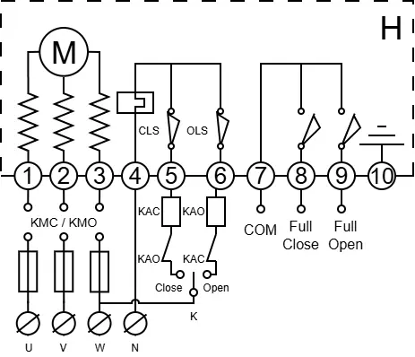
Circuit Diagram
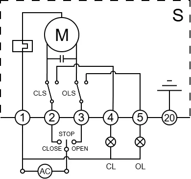
S
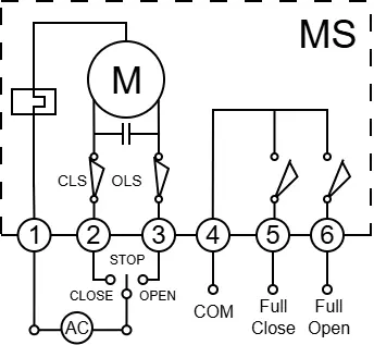
MS
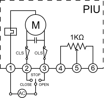
PIU
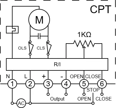
CPT
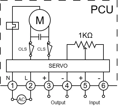
PCU
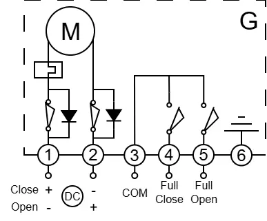
G
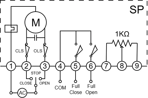
SP