Electric V-Port Control Valve
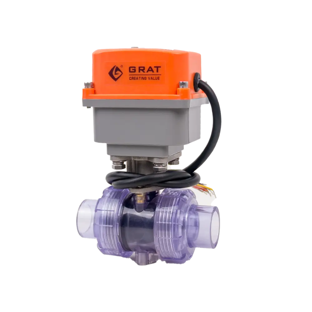
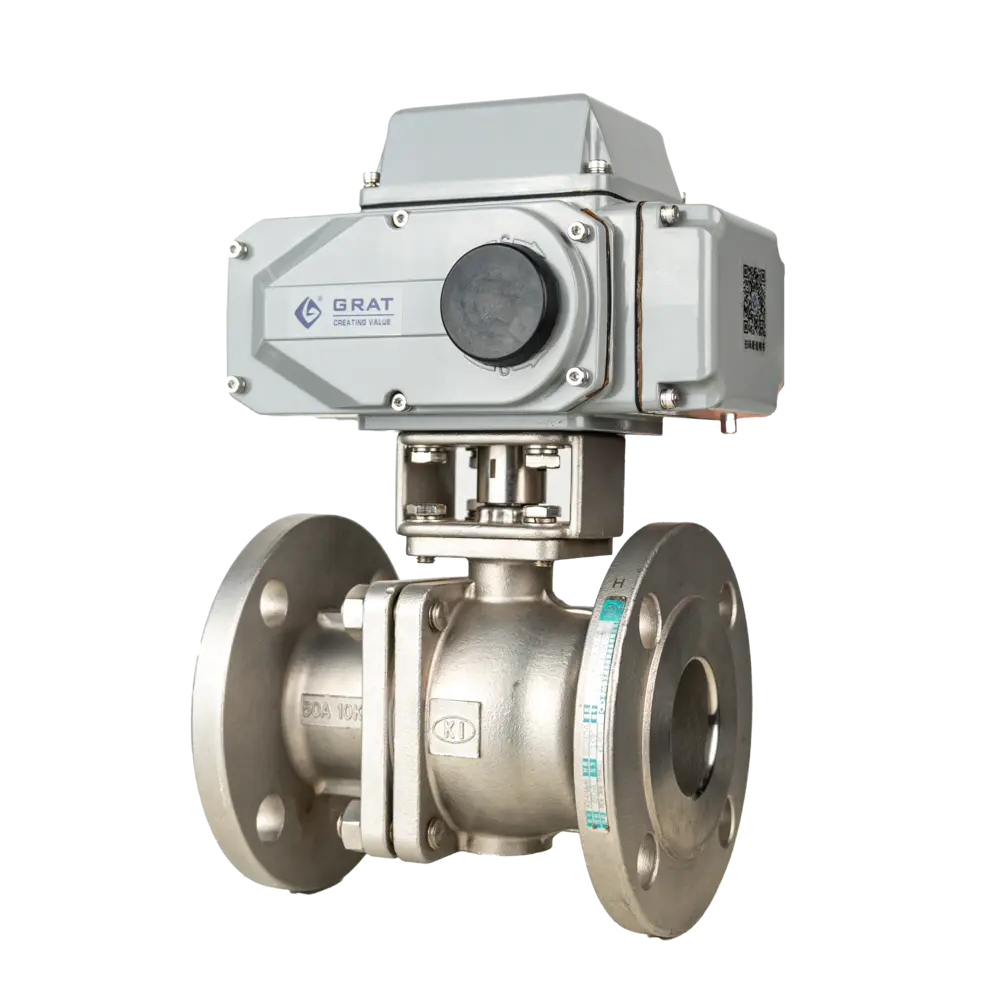
Electric V-Port Ball Valve, featuring an electric drive and a unique V-port ball design, enables precise flow regulation, cuts through media impurities, has excellent sealing, and is widely applied in industries like petrochemical, power, and metallurgy for accurate fluid control.
Tags

Features
It adopts an ultra-short flange distance structure, with the valve seat close to the end face flange, resulting in less material retention and superior sealing performance.
Compared with ordinary electric ball valves, its weight is greatly reduced to about 50% of that of ordinary electric ball valves. It features a compact structure and small volume.
The V-notch formed between the valve seat and the valve core can easily cut off various impurities in the pipeline, effectively ensuring unobstructed flow.

The valve core defines the valve characteristics. The unique V-shaped valve core structure resolves the control stability issues of traditional ball valves, enabling precise control of flow rate through the V-shaped opening of the spherical valve core.
The V-port angle is customizable to meet more precise flow shut-off characteristics and control functions.
Basic Parameters
Material Specifications
Body & Internal Components
Suitable Media
- Food
- Grease
- Fibrous Fluid
- Water
- Oil Products
- Gas
Standards Compliance
Main Parameters
| Nominal Diameter DN(mm) | 15 | 20 | 25 | 32 | 40 | 50 | 65 | 80 | 100 | 125 | 150 | 200 | |
| Cv | O-type | 24 | 44 | 84 | 122 | 198 | 320 | 443 | 595 | 1096 | 1692 | 2602 | 4212 |
| Rectangular | 8.7 | 13.4 | 20 | 32.6 | 44.3 | 70 | 114 | 134 | 186 | 270 | 462 | 688 | |
| V-type | 7.5 | 11 | 17 | 28 | 38 | 60 | 98 | 116 | 155 | 233 | 397 | 595 | |
| Flow Characteristic | Rectangular: Approximate linear V-type (Logarithmic): Equal percentageO-type: Quick opening | ||||||||||||
| Nominal Pressure | 16(1.6MPa)、40(4.0MPa)、64(6.4MPa) | ||||||||||||
| Rangeability | 50:1 100:1 300:1 | ||||||||||||
| Flange Standard | JB/T79-2015、JB/T74-2015 | ||||||||||||
| Body Material | Cast steel (ZG230-450), Stainless steel (ZG1Cr18Ni9Ti, 316, 316L), Titanium alloy | ||||||||||||
| Ball Core Material | Stainless steel (ZG1Cr18Ni9Ti, 316, 316L, A105), Titanium alloy, etc. | ||||||||||||
| Valve Stem Material | Stainless steel (ZG1Cr18Ni9Ti, 316, 316L) | ||||||||||||
| Packing Material | PTFE, Flexible graphite | ||||||||||||
| Sealing Type | Soft seal | Hard seal | |||||||||||
| Medium Temperature | ≤220℃ | ≤450℃ | |||||||||||
| Seat Material | PTFE | Carbon fiber reinforced PTFE | Stainless steel or Stainless steel + STL | ||||||||||
| Leakage Rate | Class Ⅵ | Class Ⅴ | |||||||||||
| Nominal Diameter | DN15-DN350(Contact us for larger sizes) | ||||||||||||
| Nominal Pressure | PN1.6MPa~PN6.4MPa | ||||||||||||
| Connection Type | Flanged connection, Wafer connection | ||||||||||||
| Actuation Time | 15秒、30秒(Optional)(0-90°) | ||||||||||||
| Power Supply | AC110V, AC220V,AC380V,DC24V | ||||||||||||
| Control Mode | Regulating or On-off control | ||||||||||||
| Ambient Temperature | ≤60℃ | ||||||||||||
| Applicable Medium | Food, Grease, Fibrous fluid, Water, Oil, Gas | ||||||||||||
| Dead Band | 0.3%-3.0% Adjustable | ||||||||||||
Dimension Drawing
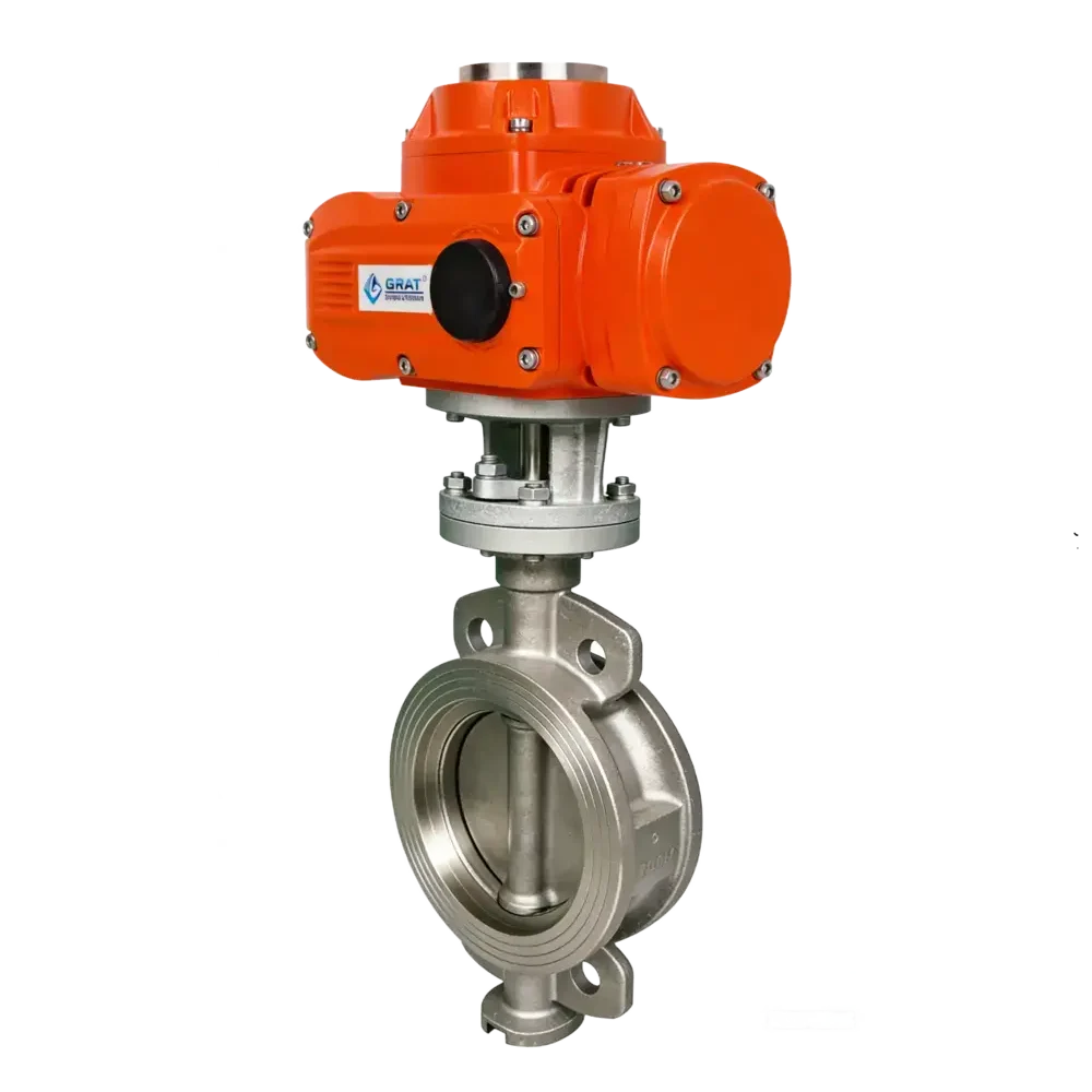
1.Outline Drawing and Connection Dimensions of Electric V-type Regulating Valve (Wafer Type)

| Nominal Diameter DN (mm) | Diameter Inch | A | φD | H1 | H2 | H | W1 | W2 |
| 15 | 1/2" | 62 | 54 | 74 | 75 | 390 | 196 | 145 |
| 20 | 3/4" | 62 | 54 | 74 | 75 | 390 | 196 | 145 |
| 25 | 1" | 62 | 54 | 74 | 75 | 390 | 196 | 145 |
| 32 | 1-1/4" | 62 | 78 | 80 | 75 | 400 | 196 | 145 |
| 40 | 1-1/2" | 62 | 82 | 85 | 75 | 405 | 196 | 145 |
| 50 | 2" | 75 | 100 | 87 | 95 | 430 | 196 | 145 |
| 65 | 2-1/2" | 80 | 120 | 105 | 115 | 498 | 255 | 182 |
| 80 | 3" | 100 | 131 | 115 | 125 | 520 | 255 | 182 |
| 100 | 4" | 115 | 158 | 125 | 125 | 530 | 255 | 182 |
| 125 | 5" | 130 | 180 | 140 | 155 | 570 | 255 | 182 |
| 150 | 6" | 160 | 216 | 153 | 165 | 600 | 255 | 182 |
| 200 | 8" | 200 | 260 | 200 | 195 | 680 | 255 | 182 |
| 250 | 10" | 240 | 325 | 225 | 225 | 730 | 255 | 182 |
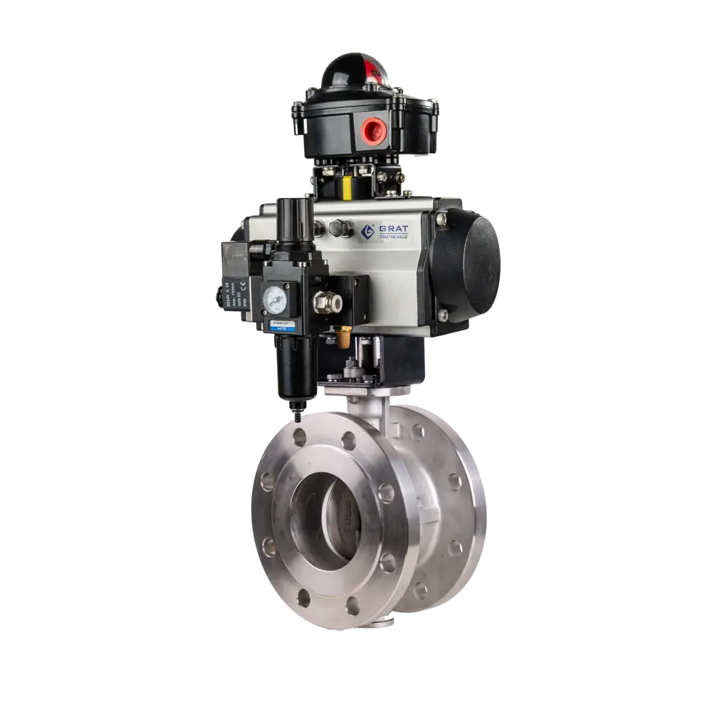
2.Outline Drawing and Connection Dimensions of Electric V-type Regulating Valve (Ultra-short Flange Type)

3.Installation Dimensions of Electric V-type Regulating Valve (Ultra-short Flange) – National Standard
Design Standard: GB/T 12237-2007
Flange Standard: GB/T 9113-2010 National Standard Unit: mm
| Nominal Diameter (DN) | d | D1 | K | D | n-Md | f | L | H | W | |
| mm | in | |||||||||
| DN15 | 1/2〃 | 15 | 45 | 65 | 95 | 4-M12 | 2 | 35 | 210 | 196 |
| DN20 | 3/4〃 | 19 | 55 | 75 | 105 | 4-M12 | 2 | 38 | 216 | 196 |
| DN25 | 1〃 | 25 | 65 | 85 | 115 | 4-M12 | 2 | 50 | 223 | 196 |
| DN32 | 1-1/4〃 | 28 | 76 | 100 | 140 | 4-M12 | 2 | 50 | 230 | 196 |
| DN40 | 1-1/2〃 | 38 | 83 | 110 | 148 | 4-M16 | 3 | 67 | 240 | 196 |
| DN50 | 2〃 | 49 | 102 | 125 | 156 | 4-M16 | 3 | 72 | 250 | 196 |
| DN65 | 2-1/2〃 | 64 | 120 | 145 | 185 | 4-M16 | 3 | 94 | 298 | 255 |
| DN80 | 3〃 | 73 | 143 | 160 | 200 | 8-M16 | 3 | 120 | 312 | 255 |
| DN100 | 4〃 | 90 | 168 | 180 | 220 | 8-M16 | 3 | 141 | 322 | 255 |
| DN125 | 5〃 | 110 | 185 | 210 | 245 | 8-M16 | 3 | 165 | 397 | 255 |
| DN150 | 6〃 | 145 | 208 | 240 | 277 | 8-M20 | 3 | 225 | 422 | 255 |
| DN200 | 8〃 | 195 | 265 | 395 | 335 | 12-M20 | 3 | 275 | 512 | 255 |
4.Installation Dimensions of Electric V-type Regulating Valve (Ultra-short Flange) – German Standard
Design Standard: DIN 3375/1, 2, EN 12516-1
Flange Standard: DIN EN 1092-1 PN10–PN40 German Standard Unit: mm
| Nominal Diameter(DN) | d | D1 | K | D | n-Md | f | L | H | W | |
| mm | in | |||||||||
| DN15 | 1/2〃 | 15 | 45 | 65 | 95 | 4-M12 | 2 | 44 | 220 | 196 |
| DN20 | 3/4〃 | 20 | 58 | 75 | 105 | 4-M12 | 2 | 44 | 220 | 196 |
| DN25 | 1〃 | 25 | 68 | 85 | 115 | 4-M12 | 2 | 50 | 223 | 196 |
| DN32 | 1-1/4〃 | 32 | 78 | 100 | 140 | 4-M16 | 2 | 60 | 237 | 196 |
| DN40 | 1-1/2〃 | 38 | 88 | 110 | 150 | 4-M16 | 3 | 65 | 244 | 196 |
| DN50 | 2〃 | 49 | 102 | 125 | 165 | 4-M16 | 3 | 80 | 245 | 196 |
| DN65 | 2-1/2〃 | 62 | 122 | 145 | 185 | 4-M16 | 3 | 110 | 306 | 255 |
| DN80 | 3〃 | 74 | 138 | 160 | 200 | 8-M16 | 3 | 120 | 326 | 255 |
| DN100 | 4〃 | 100 | 158 | 180 | 220 | 8-M16 | 3 | 152 | 338 | 255 |
| DN125 | 5〃 | 118 | 188 | 210 | 250 | 8-M16 | 3 | 180 | 363 | 255 |
| DN150 | 6〃 | 150 | 212 | 240 | 285 | 8-M20 | 3 | 232 | 396.5 | 255 |
5.Outline Drawing and Connection Dimensions of Electric V-type Regulating Valve (Long Flange Type)

| Nominal Diameter(DN) | L | D | K | D1 | n-Φd | b | i | H | W | |
| mm | in | |||||||||
| 15 | 1/2″ | 130 | 95 | 65 | 45 | 4-Φ14 | 14 | 2 | 209 | 196 |
| 20 | 3/4″ | 130 | 105 | 75 | 55 | 4-Φ14 | 16 | 2 | 211 | 196 |
| 25 | 1″ | 142 | 113 | 85 | 65 | 4-Φ14 | 18 | 2 | 218.5 | 196 |
| 32 | 1-1/4″ | 165 | 140 | 100 | 78 | 4-Φ18 | 18 | 2 | 233 | 196 |
| 40 | 1-1/2″ | 165 | 150 | 110 | 85 | 4-Φ18 | 18 | 2 | 234 | 196 |
| 50 | 2″ | 203 | 165 | 125 | 100 | 4-Φ18 | 20 | 2 | 248 | 196 |
| 65 | 2-1/2″ | 222 | 185 | 145 | 120 | 8-Φ18 | 20 | 2 | 294 | 255 |
| 80 | 3″ | 241 | 200 | 160 | 135 | 8-Φ18 | 21 | 2 | 320 | 255 |
| 100 | 4″ | 305 | 220 | 180 | 155 | 8-Φ18 | 22 | 2 | 339 | 255 |
| 125 | 5″ | 356 | 250 | 210 | 184 | 8-Φ18 | 22 | 3 | 392 | 255 |
| 150 | 6″ | 394 | 285 | 240 | 210 | 8-Φ23 | 24 | 3 | 402 | 255 |
| 200 | 8″ | 457 | 340 | 295 | 265 | 12-Φ23 | 26 | 3 | 467 | 255 |
7.Installation Dimensions of Electric V-type Regulating Valve (Long Flange) – Japanese Standard
Design Standard: API B2002
Flange Standard: JIS B2220-2004 Japanese Standard Unit: mm
| DN | in | L | D | K | D1 | b | i | n-Φd | H | W |
| 15 | 1/2" | 108 | 95 | 70 | 51 | 12 | 2 | 4-15 | 209 | 196 |
| 20 | 3/4" | 117 | 100 | 75 | 56 | 14 | 2 | 4-15 | 213 | 196 |
| 25 | 1" | 127 | 125 | 90 | 67 | 14 | 2 | 4-19 | 221 | 196 |
| 32 | 1.2" | 140 | 135 | 100 | 76 | 16 | 2 | 4-19 | 229 | 196 |
| 40 | 1.5" | 165 | 140 | 105 | 81 | 16 | 2 | 4-19 | 239 | 196 |
| 50 | 2" | 178 | 155 | 120 |
8.Installation Diagram of Electric V-type Ball Valve and Pipeline

Circuit Diagram

S

MS

PIU

CPT

PCU

G

SP