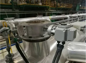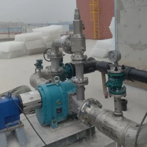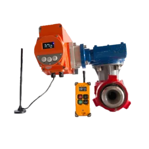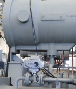
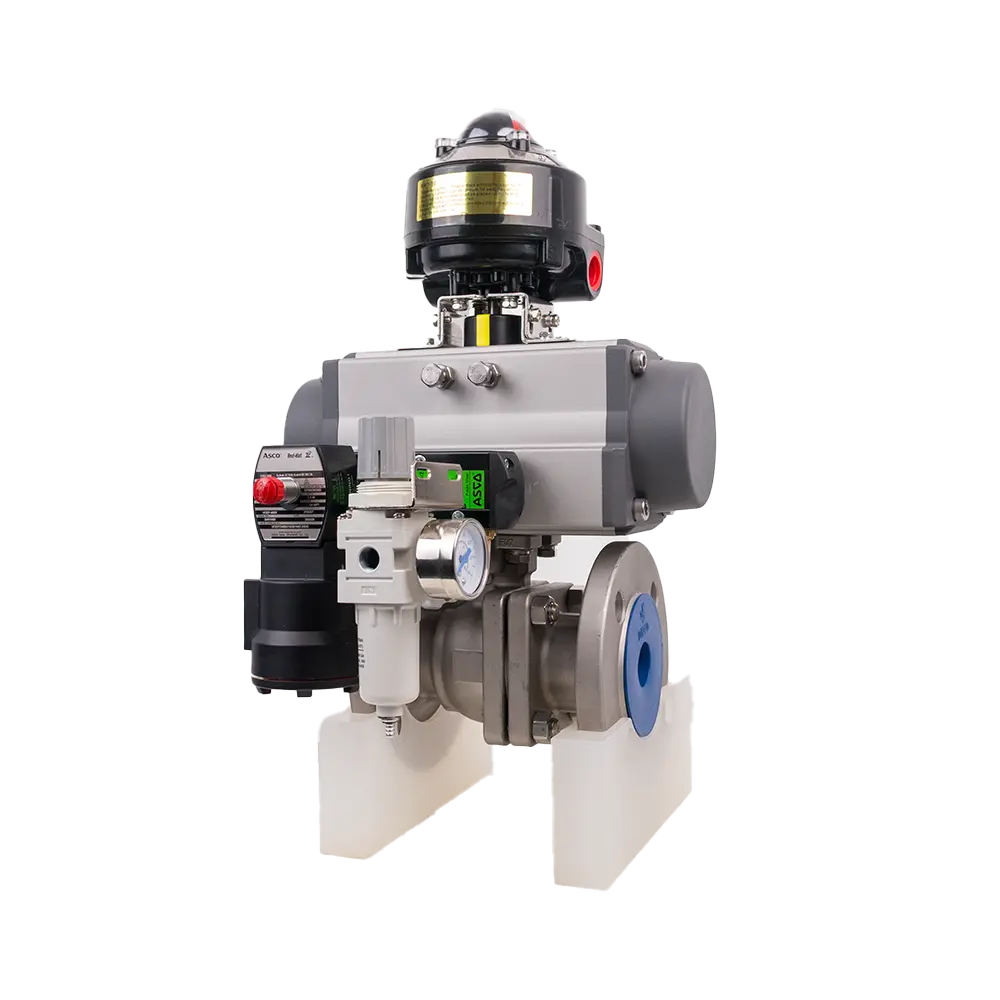
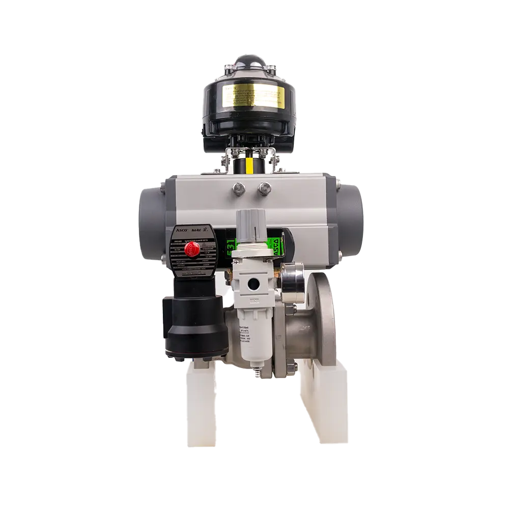
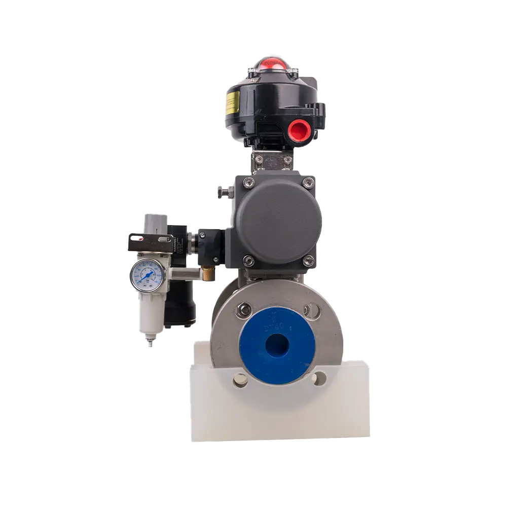
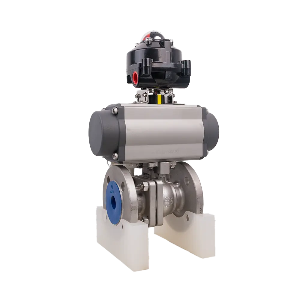
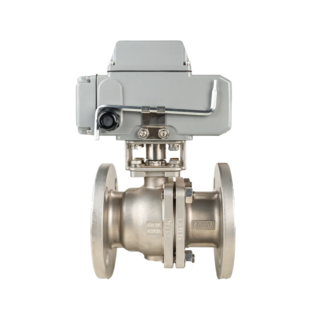

Pneumatic Flange Ball Valve
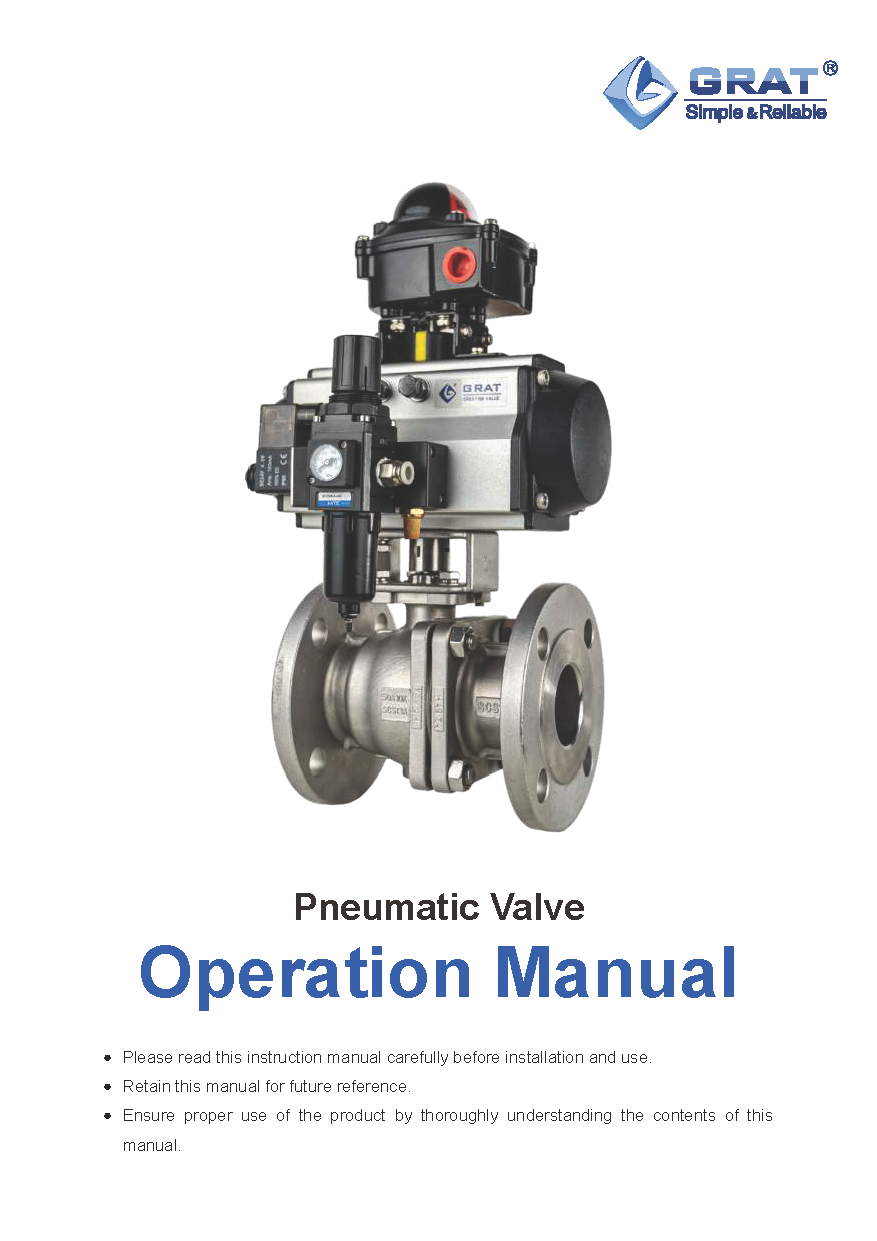
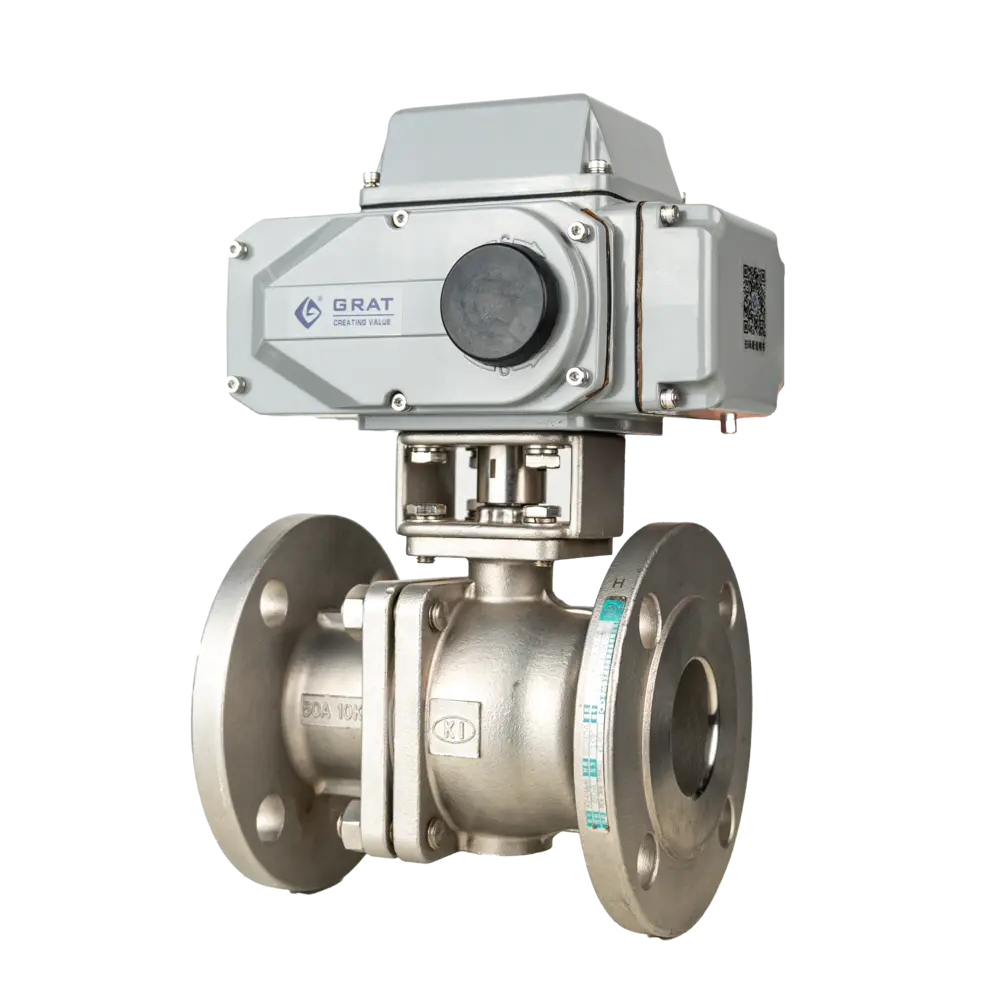
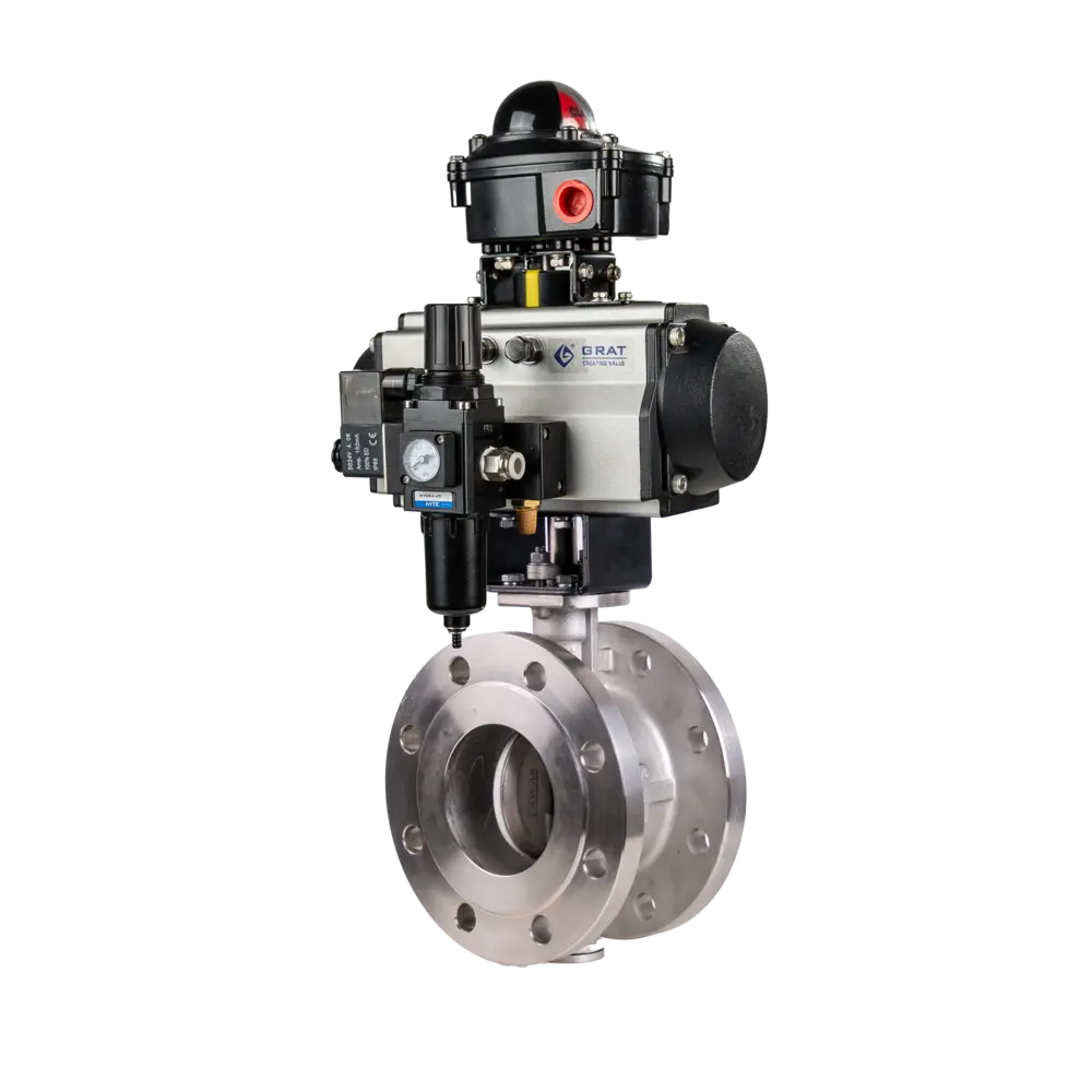
Pneumatic flanged ball valves use a quarter-turn (0–90°) pneumatic actuator to rotate the ball for open/close operation. They provide leak-tight shutoff and low pressure drop, are compatible with a wide range of media, and are widely used in industrial process control — including petrochemical and metallurgical applications.
Tags
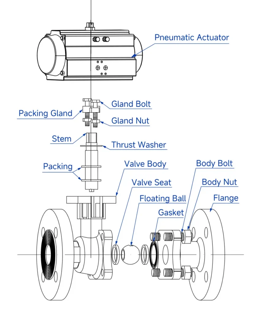
Features
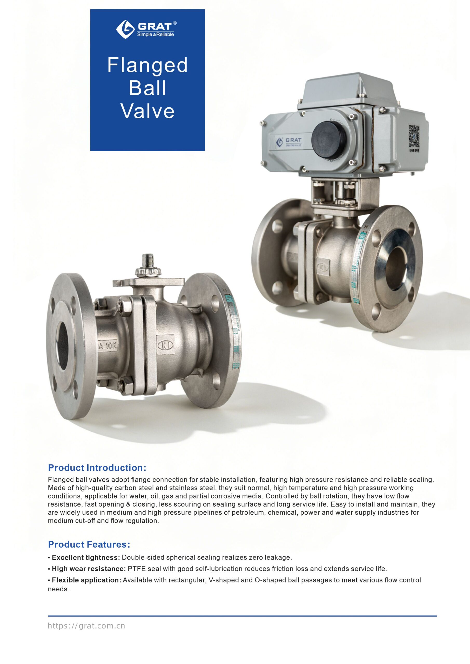
- Leak-tight shutoff — Dual-seat (floating ball) design delivers bubble-tight, zero-leakage isolation of the media.
- Extended service life — PTFE seats are self-lubricating and low-friction against the ball, minimizing wear and extending cycle life.
- Flexible flow control — Ball ports in full-bore (O-type), V-type, and rectangular configurations adapt to both on/off and throttling duties.
Basic Parameters
Nominal Diameter (DN):
DN15 - DN200
Operating Power Supply:
AC110V, AC220V, AC380V, DC24V
Medium Temperature:
-20°C to 350°C
(Special sealing for >200°C)
Working Pressure:
PN1.0 ~ 10.0MPa
Control Method:
Modulating or On/Off Control
Protection Class:
IP67
Connection & Sealing
Connection Type:
Flange Type
Sealing Type:
Elastic Seal, High-Temperature Resistant PPS (Polyphenylene Sulfide), Hard Alloy & Industrial Ceramics
Leakage Rate:
Complies with ANSI B16.104 Class 5 Standard
Material Specifications
Body & Internal Components
Body Material:
A105, F304, F316, WCB, FZG1Cr18Ni9Ti, ZG1Cr18Ni12Mo2Ti, CF8, CF8M, CF3M
Ball Material:
SUS304, SUS316
Sealing Components
Seat Material:
PTFE (Normal Temperature)
Special PPL (High Temperature)
Metal Seal (High Temperature)
Applicable Medium
- Water
- Petroleum
- Nitric Acid
- Acetic Acid
- Viscous Fluids
- Slurries
- Strong Oxidizing Media
Standards Compliance
Design & Manufacturing:
GB 12237-2007, API 6D
Flange Standards:
- JB/T 79-2015
- GB/T 9124.1-2019
- GB/T 9124.2-2019
- ANSI B16.5
- JIS B2239
Face-to-Face Dimension:
GB 12221-2005
Inspection Standard:
API 598
Main Parameters
| Power Supply | AC110V, AC220V, AC380V, DC24V |
| Nominal Diameter | DN15-200 |
| Medium Temperature | -20℃ to +350℃ (+200℃ for special seal) |
| Working Pressure | PN1.0~10.0MPa |
| Control Mode | Regulation or On-Off Control |
| Pneumatic Actuation | Single-acting (with spring return) or Double-acting |
| Connection Type | Flanged |
| Body Material | A105, F304, F316, WCB, FZG1Cr18Ni9Ti, ZG1Cr18Ni12Mo2Ti, CF8, CF8M, CF3M |
| Seat Material | PTFE (normal temperature), Special PPL (high temperature), Metal seal (high temperature) |
| Leakage Class | ANSI B16.104 Class 5 |
| Sealing Type | Elastic seal, High temperature resistant polyphenylene, Hard alloy, Industrial ceramic |
| Applicable Medium | Water, Petroleum, Nitric acid, Acetic acid, Viscous fluid, Slurry, Strong oxidizing medium |
| Protection Grade | IP67 |
| Design and Manufacturing Standard | GB12237-2021, API 6D |
| Flange Standard | JB/T 79-2015, GB/T 9124.1-2019, GB/T 9124.2-2019, ANSI B16.5, JIS B2239 |
| Face-to-Face Dimension | GB12221-2005 |
| Inspection Standard | API 598 |
Dimension Drawing
1.Installation Dimension Drawing of Pneumatic Flanged Ball Valve (Standard)
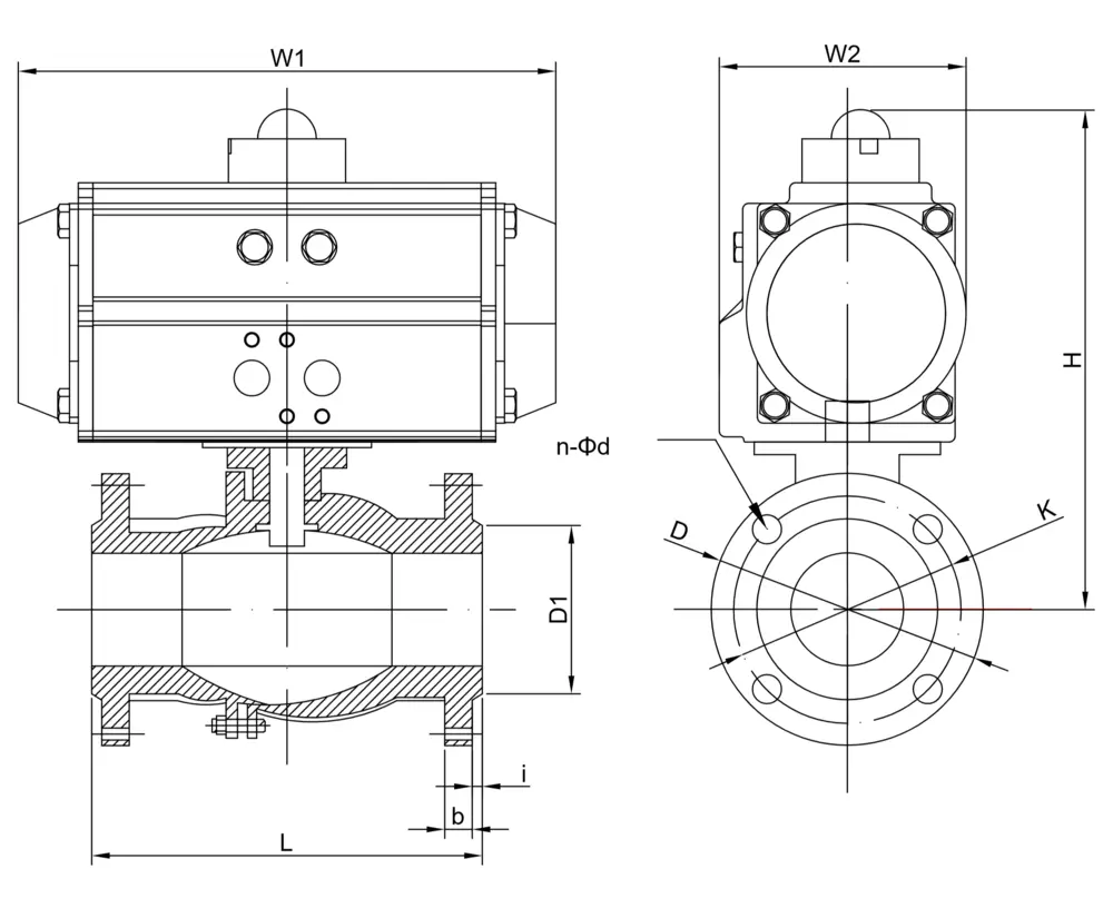
| Nominal Diameter (DN)) | L | D | K | D1 | n-Φd | b | i | Double Acting | Single Acting | |||||
| H | W1 | W2 | H | W1 | W2 | |||||||||
| mm | in | |||||||||||||
| 15 | 1/2″ | 130 | 95 | 65 | 45 | 4-Φ14 | 14 | 2 | 195 | 147 | 72 | 195 | 147 | 72 |
| 20 | 3/4″ | 130 | 105 | 75 | 55 | 4-Φ14 | 16 | 2 | 197 | 147 | 72 | 213 | 168 | 83 |
| 25 | 1″ | 142 | 113 | 85 | 65 | 4-Φ14 | 18 | 2 | 221 | 168 | 83 | 233 | 184 | 95 |
| 32 | 1 1/4″ | 165 | 140 | 100 | 78 | 4-Φ18 | 18 | 2 | 235 | 168 | 83 | 256 | 204 | 103 |
| 40 | 1 1/2″ | 165 | 150 | 110 | 85 | 4-Φ18 | 18 | 2 | 248 | 184 | 95 | 265 | 262 | 109 |
| 50 | 2″ | 203 | 165 | 125 | 100 | 4-Φ18 | 20 | 2 | 271 | 204 | 103 | 295 | 268 | 122 |
| 65 | 2 1/2″ | 222 | 185 | 145 | 120 | 8-Φ18 | 20 | 2 | 325 | 262 | 109 | 383 | 301 | 142 |
| 80 | 3″ | 241 | 200 | 160 | 135 | 8-Φ18 | 21 | 2 | 345 | 268 | 122 | 404 | 390 | 152 |
| 100 | 4″ | 305 | 220 | 180 | 155 | 8-Φ18 | 22 | 2 | 406 | 301 | 142 | 448 | 458 | 174 |
| 125 | 5″ | 356 | 250 | 210 | 184 | 8-Φ18 | 22 | 3 | 459 | 301 | 142 | 501 | 458 | 174 |
| 150 | 6″ | 394 | 285 | 240 | 210 | 8-Φ23 | 24 | 3 | 486 | 390 | 152 | 544 | 525 | 206 |
| 200 | 8″ | 457 | 340 | 295 | 265 | 12-Φ23 | 26 | 3 | 576 | 458 | 174 | 634 | 532 | 226 |
Note: The suitable actuator model may vary for pneumatic valves depending on the service medium, valve torque and control method, resulting in corresponding changes to relevant dimensions.
1、Pneumatic Control Valve
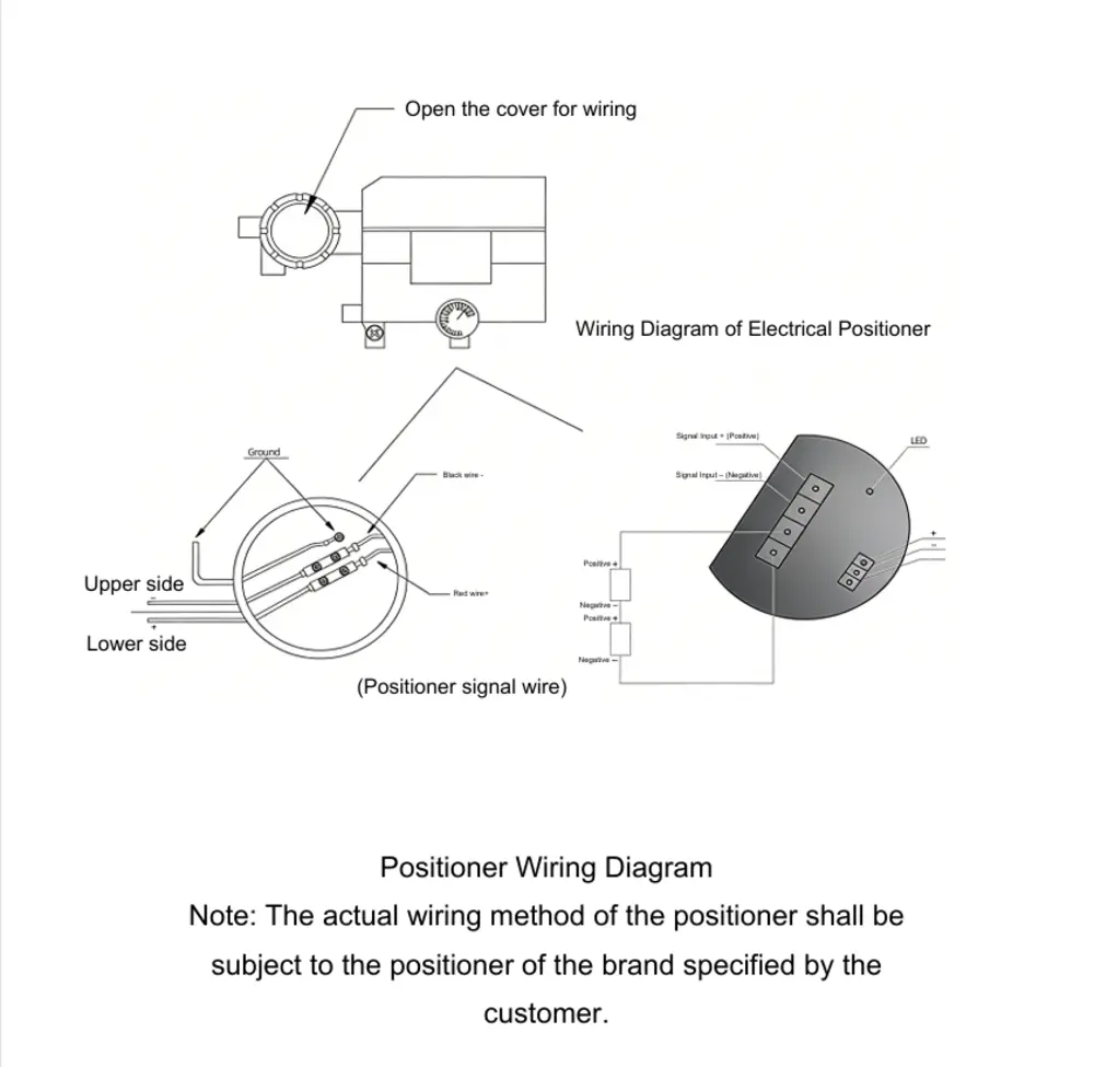
2、Pneumatic On-Off Valve