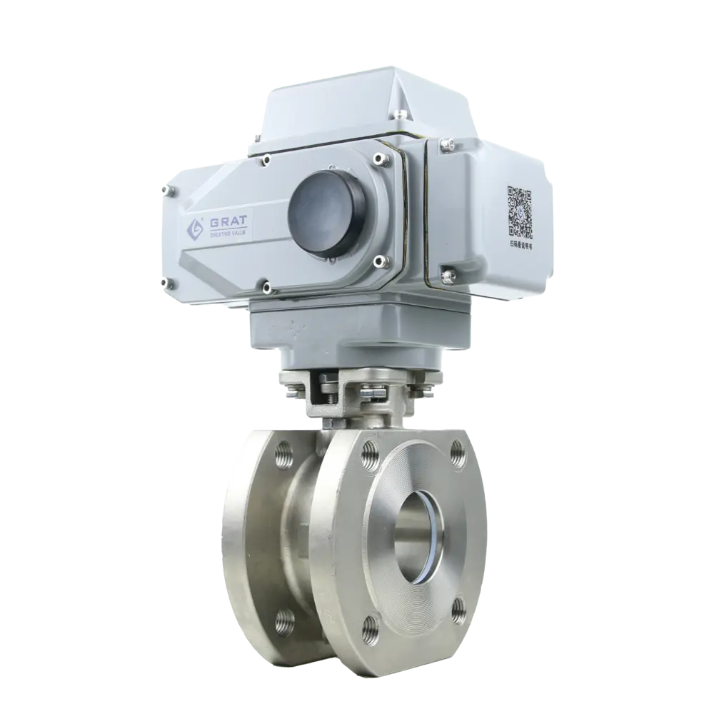
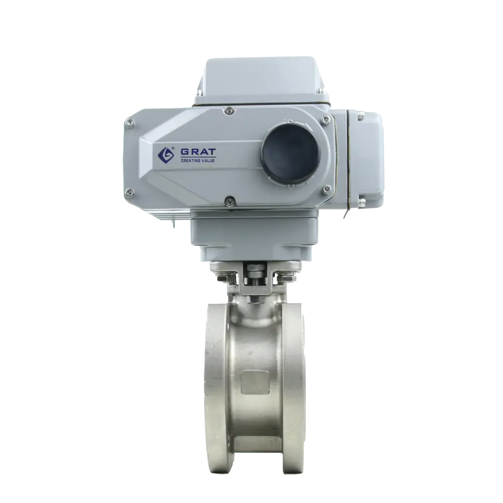
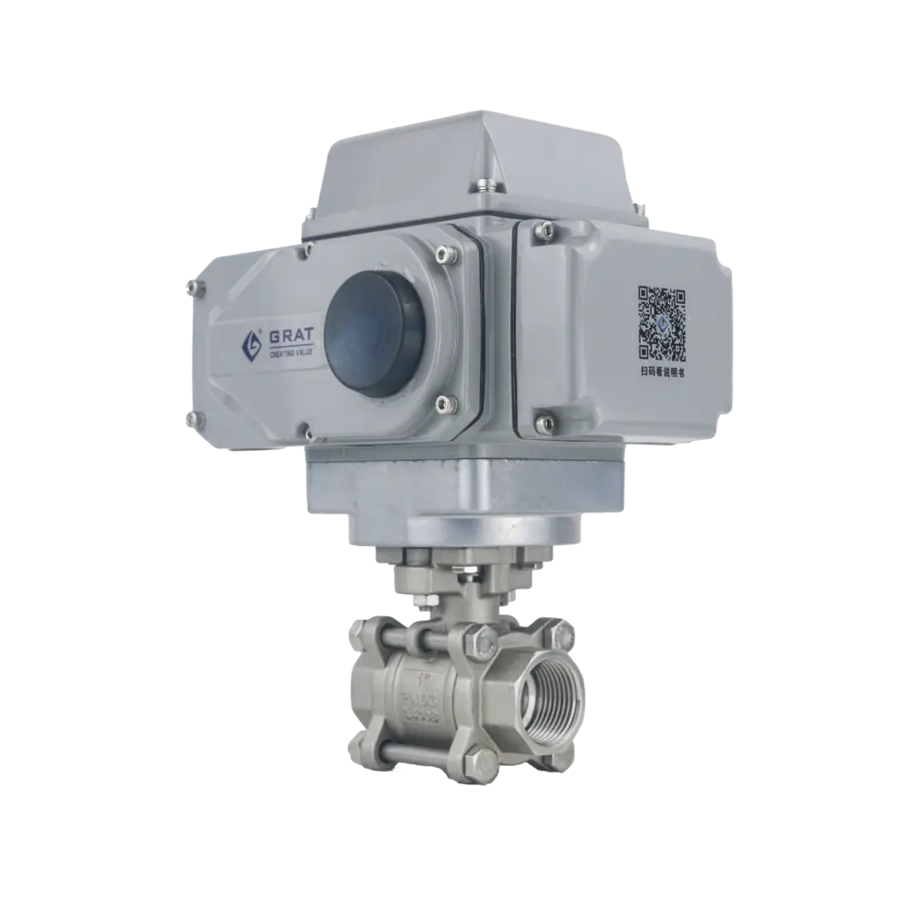
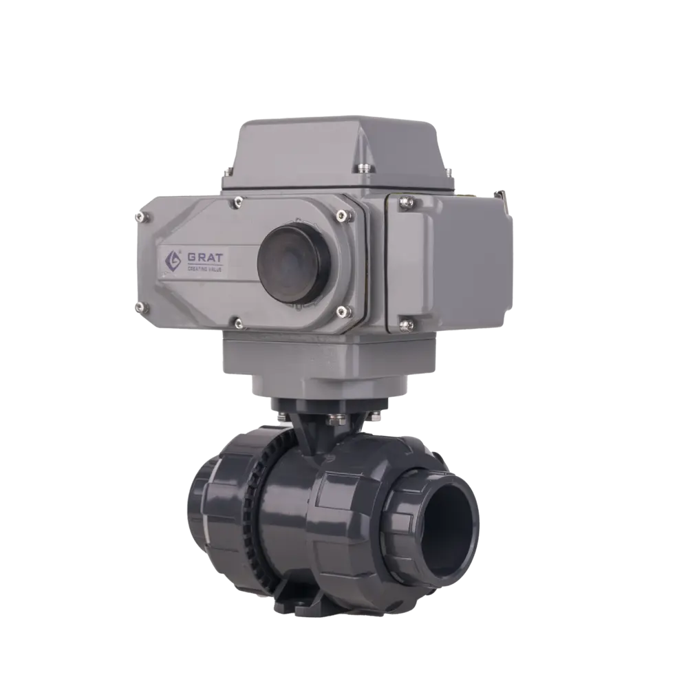
Quick-opening Electric Ball Valve
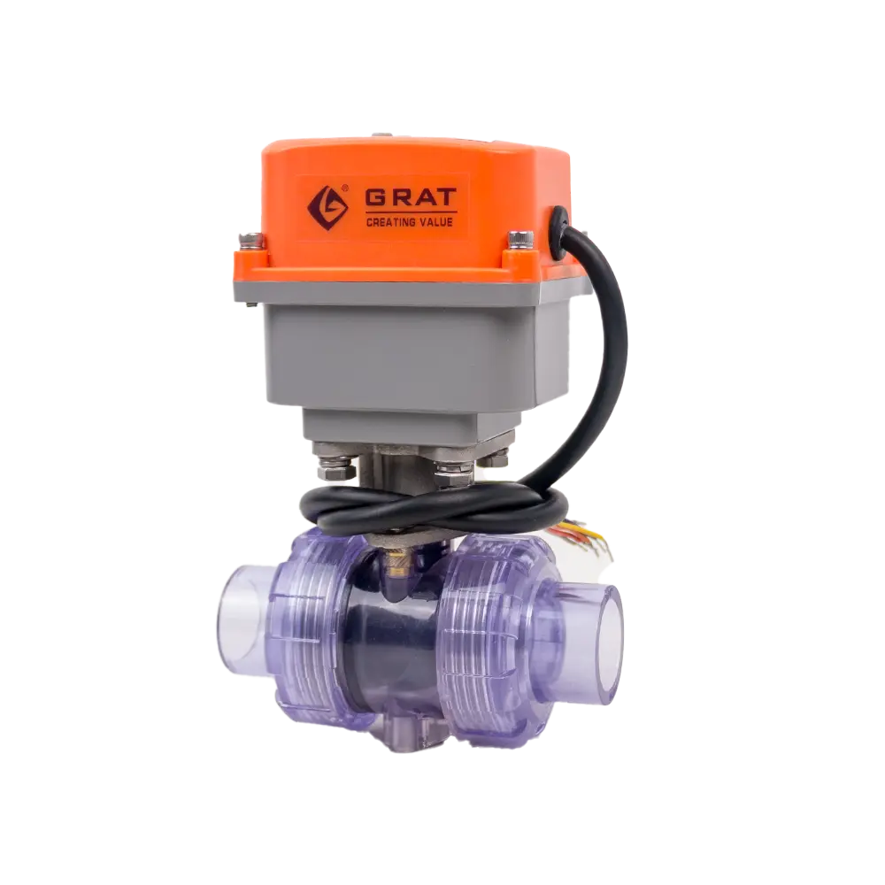
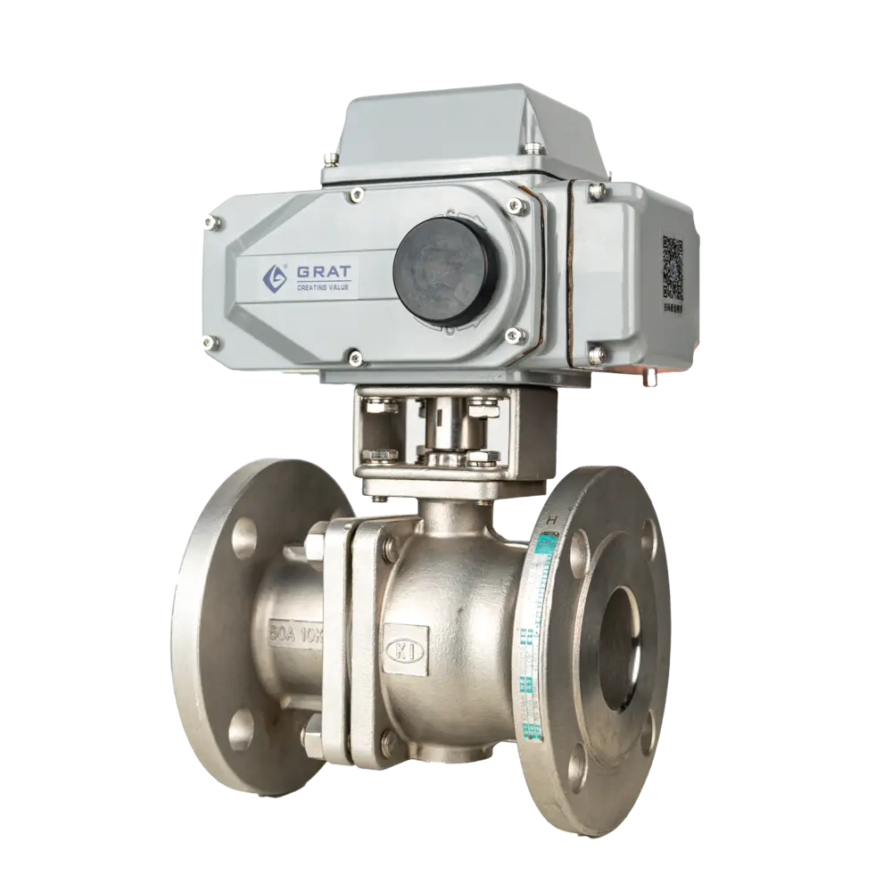
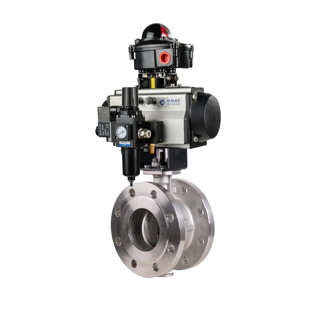
The Quick-opening Electric Ball Valve is an automated flow control device for rapid actuation (typically 3–8 s) in industrial pipelines. It pairs an electric actuator with a precision ball valve for instant on/off operation, and is ideal for fast-response applications in water treatment, chemical plants, power generation, and HVAC.
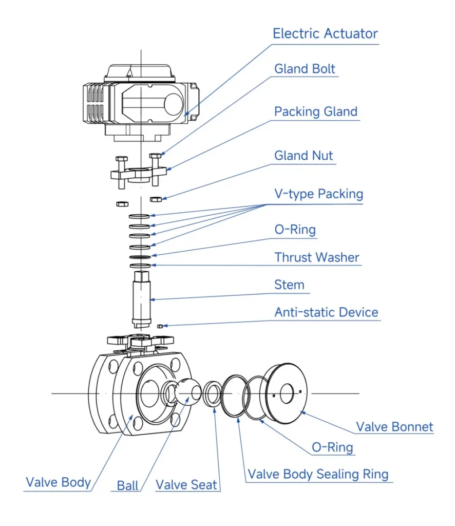
Features
- Fast cycle — Completes open/close in just 4 seconds.
- Energy-saving actuator — The quick-opening electric actuator draws power only during operation, with zero standby consumption, lowering system operating costs.
- Simple operation — Easy to operate and fast acting; a 90° turn runs from fully open to fully closed, enabling remote control.
- Versatile and compact — Multiple end connections available (flanged, threaded, double-union, and more). Compact, lightweight, reliable, and easy to configure.
- Low pressure drop, high flow — Full-bore designs have near-zero pressure drop. Ball valves offer the lowest flow resistance of any valve type; even reduced-bore versions have very low resistance.
Main Parameters
| Nominal Diameter | DN15~DN100 |
| Power Supply | AC110V, AC220V,AC380V, DC24V |
| Medium Temperature | ≤220℃ |
| Ambient Temperature | -30℃-60℃ |
| Nominal Pressure | 0.1~6.4MPa |
| Operation Mode | On-off Shut-off |
| Operating Time | 2、4、6S |
| Applicable Media | Water, Oil Products, Gas |
| Connection Type | Flange Connection, Threaded Connection, Double Union Connection (Max. Pressure Resistance: 1.6MPa) |
| Sealing Type | Double-sided Spherical Seal (Zero Leakage) |
| Body Material | WCB、SUS304、SUS316 |
| Seal Ring Material | PTFE、PPL,Metal Hard Seal |
| Protection Class | IP67 |
| Manufacturing Standards | GB12237-2021、API 6D |
| Flange Standards | JB/T 79-2015、GB/T 9124.1-2019、GB/T 9124.2-2019、ANSI B16.5、JIS B2239 |
| Face-to-Face Dimension Standard | GB12221-2005 |
| Inspection Standard | API 598 |
Installation Dimensions of Electric Ball Valve
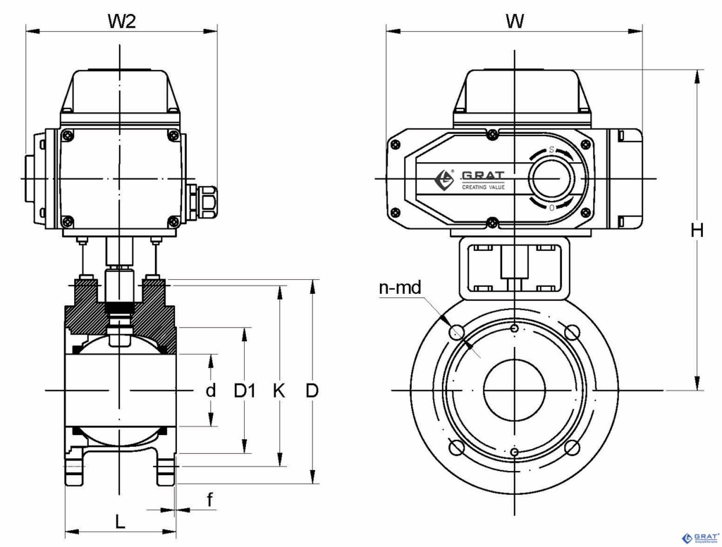
Quick-Opening Electric Ball Valve - Installation Dimensions
Chinese National Standard (GB)
- Design Standard: GB/T 12237-2007
- Flange Standards: GB/T 9124.1-2019, GB/T 9124.2-2019
- Unit (GB): (mm)
| Nominal Diameter | d | D1 | K | D | n-Md | f | L | H | W | W2 | |
| mm | in | ||||||||||
| DN15 | 1/2" | 15 | 45 | 65 | 95 | 4-M12 | 2 | 35 | 210 | 196 | 145 |
| DN20 | 3/4" | 19 | 55 | 75 | 105 | 4-M12 | 2 | 38 | 216 | 196 | 145 |
| DN25 | 1" | 25 | 65 | 85 | 115 | 4-M12 | 2 | 50 | 223 | 196 | 145 |
| DN32 | 1-1/4" | 28 | 76 | 100 | 140 | 4-M12 | 2 | 50 | 230 | 196 | 145 |
| DN40 | 1-1/2" | 38 | 83 | 110 | 148 | 4-M16 | 3 | 67 | 240 | 196 | 145 |
| DN50 | 2" | 49 | 102 | 125 | 156 | 4-M16 | 3 | 72 | 250 | 196 | 145 |
| DN65 | 2-1/2" | 64 | 120 | 145 | 185 | 4-M16 | 3 | 94 | 298 | 255 | 145 |
| DN80 | 3" | 73 | 143 | 160 | 200 | 8-M16 | 3 | 120 | 312 | 255 | 182 |
| DN100 | 4" | 90 | 168 | 180 | 220 | 8-M16 | 3 | 141 | 322 | 255 | 182 |
German National Standard (DIN)
- Design Standards: DIN 3375/1, 2, EN 12516-1
- Flange Standard: DIN EN 1092-1 PN10-PN40
- Unit (DIN): (mm)
| Nominal Diameter | d | D1 | K | D | n-Md | f | L | H | W | W2 | |
| mm | in | ||||||||||
| DN15 | 1/2" | 15 | 45 | 65 | 95 | 4-M12 | 2 | 44 | 220 | 196 | 145 |
| DN20 | 3/4" | 20 | 58 | 75 | 105 | 4-M12 | 2 | 44 | 220 | 196 | 145 |
| DN25 | 1" | 25 | 68 | 85 | 115 | 4-M12 | 2 | 50 | 223 | 196 | 145 |
| DN32 | 1-1/4" | 32 | 78 | 100 | 140 | 4-M16 | 2 | 60 | 237 | 196 | 145 |
| DN40 | 1-1/2" | 38 | 88 | 110 | 150 | 4-M16 | 3 | 65 | 244 | 196 | 145 |
| DN50 | 2" | 49 | 102 | 125 | 165 | 4-M16 | 3 | 80 | 245 | 196 | 145 |
| DN65 | 2-1/2" | 62 | 122 | 145 | 185 | 4-M16 | 3 | 110 | 306 | 255 | 182 |
| DN80 | 3" | 74 | 138 | 160 | 200 | 8-M16 | 3 | 120 | 326 | 255 | 182 |
| DN100 | 4" | 100 | 158 | 180 | 220 | 8-M16 | 3 | 152 | 338 | 255 | 182 |
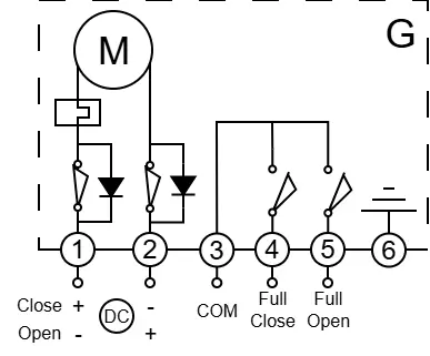
Circuit Diagram
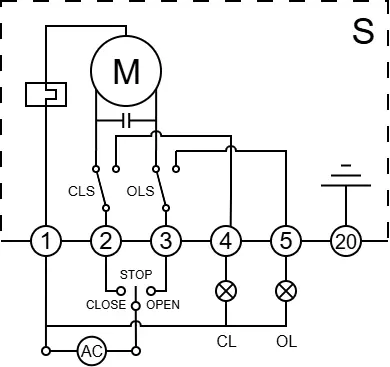
S
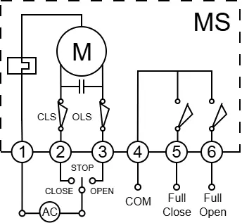
MS