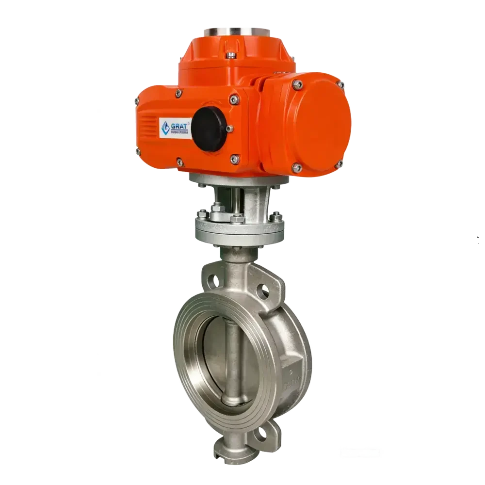
Explosion-proof Soft-sealed Butterfly Valve
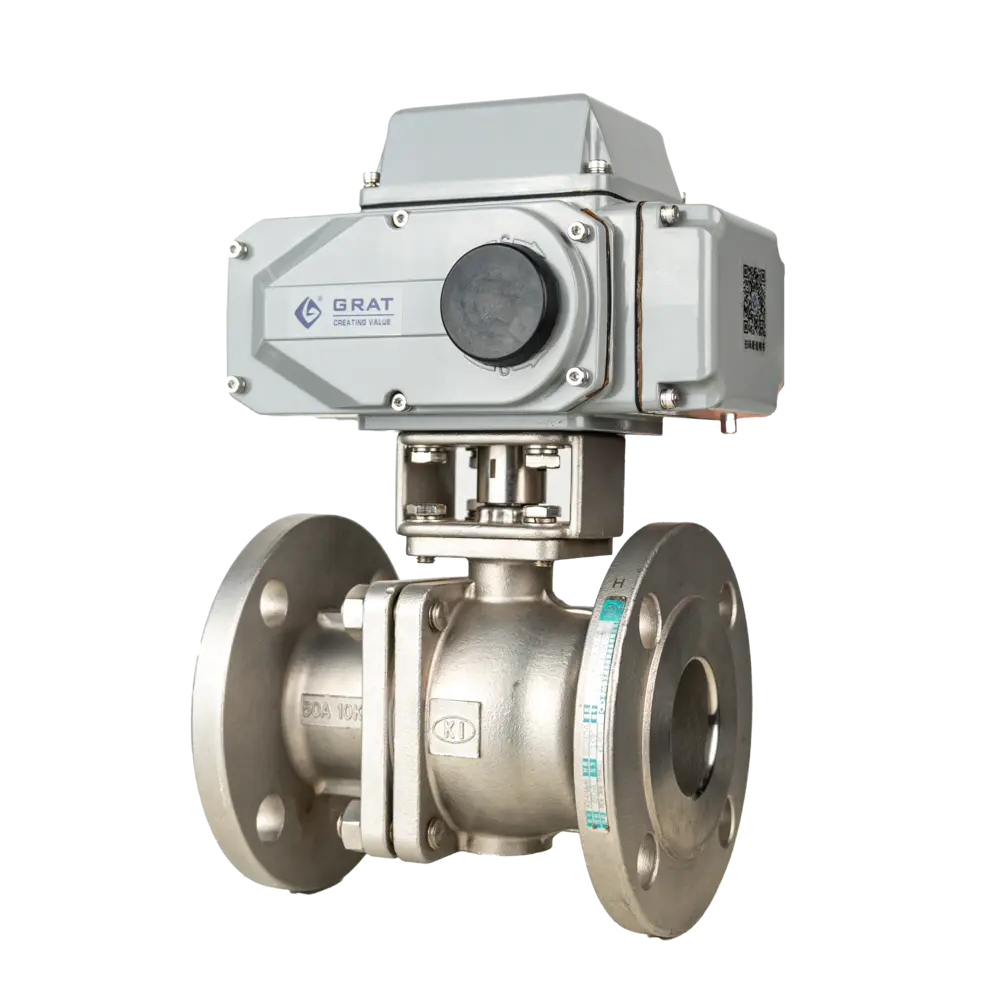
The Explosion-proof Electric Butterfly Valve is an automated control valve specifically designed for flammable and explosive environments. It combines the compact structure of a wafer butterfly valve with an explosion-proof electric actuator, making it widely used in high-risk industrial sectors such as petroleum, natural gas, and chemical processing.
Tags

特点
- It adopts a pinless structure, which effectively prevents pin detachment during long-term operation.
- This valve features bidirectional sealing, and its installation is not restricted by the flow direction of the medium or spatial position. It can be installed in any orientation.
- The sealing pair is made of stainless steel and nitrile oil-resistant rubber, which effectively extends the service life.
- It features remarkable cost-effectiveness, especially for large-diameter butterfly valves (the preferred choice for medium and low-pressure applications).
- Due to its superior economic performance, butterfly valves are widely used in industrial automatic control systems in industries such as food, environmental protection, light industry, petroleum, papermaking, chemical engineering, shipbuilding, urban water supply and drainage, electric power, and others.
Basic Parameters
Nominal Bore (DN):
DN40~800
Operating Power:
AC110V / AC220V / AC380V / DC24V
Medium Temperature:
-20℃~+120℃
Ambient Temperature:
-30℃~+60℃
Nominal Pressure:
0.1~2.5MPa
Actuation Time:
15S / 30S / 60S
Control Method:
Modulating or On/Off Control
Connection & Sealing
Connection Types:
- Wafer Type
- Flange Type
Seal Types:
Soft Seal
Test Pressure - Shell:
1.76MPa
Test Pressure - Seal:
2.4MPa
Material Specifications
Body & Internal Components
Body Material:
WCB, QT450-10, HT200, HT250, SUS304, SUS316
Disc Material:
WCB, QT450-10, HT200, HT250, SUS304, SUS316
Shaft Material:
2Cr13
Sealing Components
Sealing Ring:
Nitrile Oil-Resistant Rubber, EPDM, PTFE, PPL, etc.
Stem Seal:
NBR, HNBR
Packing:
Flexible Graphite
Suitable Media
- Water
- Oil
- Gas
- Corrosive Medium
- Other Media
Explosion Protection
Ex db ⅡC T6 Gb
Flameproof enclosure with increased safety
Explosion Protection
Flameproof (d) + Increased Safety (b)
Gas Group
ⅡC (Hydrogen, Acetylene)
Temperature Class
T6 (≤85°C)
Equipment Protection Level
Gb (Zone 1 & 2)
Standards Compliance
Design:
GB/T 12238-2008
Flange:
- GB/T 9124.1-2019
- GB/T 9124.2-2019
- GB/T 17241.6-2008
Face-to-Face:
GB/T 12221-2005
Testing:
GB/T 13927-2008
Main Parameters
| Nominal Diameter | DN40~DN800 |
| Power Supply | AC110V, AC220V, AC380V, DC24V |
| Medium Temperature | -20~120℃ |
| Ambient Temperature | -30℃~60℃ |
| Nominal Pressure | 0.1~2.5MPa |
| Actuating Time | 15S / 30S / 60S |
| Applicable Medium | Water, oil, gas, corrosive medium, etc. |
| Control Mode | On-off or modulating control |
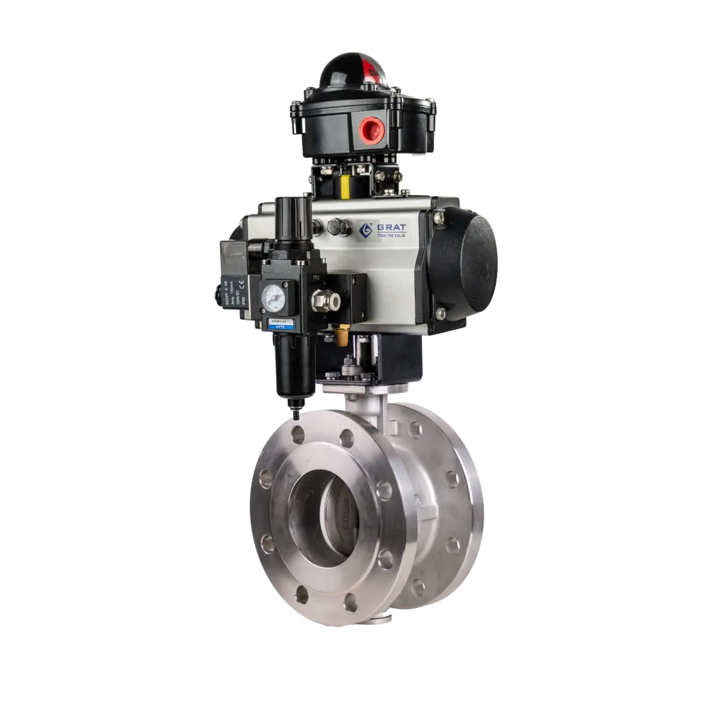
| Pneumatic Actuation | Single acting (with spring return) or double acting |
| Connection Type | Wafer type / Flange type |
| Sealing Type | Soft seal |
| Test Pressure | Shell test: 1.76MPa |
| Seal test: 2.4MPa | |
| Body Material | WCB, QT450-10, HT200, HT250, SUS304, SUS316 |
| Disc Material | WCB, QT450-10, HT200, HT250, SUS304, SUS316 |
| Shaft Material | 2Cr13 |
| Seal Ring Material | NBR (oil-resistant), EPDM, PTFE, PPL, etc. |
| Stem Seal | NBR, HNBR |
| Packing Material | Flexible graphite |
| Protection Grade | IP67 |
| Design Standard | GB/T 12238-2008 |
| Flange Standard | GB/T 9124.1-2019, GB/T 9124.2-2019, GB/T 17241.6-2008 |
| Face-to-Face Standard | GB/T 12221-2005 |
| Inspection Standard | GB/T 13927-2022 |
Dimension Drawing
1.Installation Dimension Chart of Wafer Type Explosion-proof Electric Butterfly Valve

| Nominal Diameter DN(mm) | L | D | N-φD | H2 | H1 | W2 | W1 |
| 40 | 33 | 125 | 4-Φ18 | 48 | 276 | 217 | 150 |
| 50 | 42.6 | 125 | 4-Φ18 | 70 | 398 | 217 | 150 |
| 65 | 45.6 | 145 | 4-φ18 | 76 | 375 | 217 | 150 |
| 80 | 45.6 | 160 | 8-φ18 | 89 | 381 | 217 | 150 |
| 100 | 51.6 | 180 | 4-φ22 | 104 | 414 | 217 | 150 |
| 125 | 55.6 | 210 | 4-φ22 | 120 | 429 | 217 | 150 |
| 150 | 55.6 | 240 | 4-φ23 | 139 | 465 | 217 | 150 |
| 200 | 59.6 | 295 | 4-φ23 | 175 | 536 | 268 | 180 |
| 250 | 67.6 | 355 | 4-φ28 | 203 | 562 | 268 | 180 |
| 300 | 77.6 | 410 | 4-φ28 | 242 | 561 | 268 | 180 |
| 350 | 77 | 470 | 4-φ28 | 277.5 | 562 | 268 | 180 |
| 400 | 86.5 | 525 | 4-φ30 | 309 | 613 | 354 | 273 |
| 450 | 105.6 | 585 | 4-φ30 | 337 | 633 | 354 | 273 |
| 500 | 131.8 | 650 | 4-φ33 | 361 | 693 | 354 | 273 |
Wafer Type Compatible Flange

| Nominal Diameter (mm) | D | D1 | D2 | D3 | D4 | n-Φ | H | f | D5 | b |
| 50 | 165 | 125 | 59 | 52 | 52 | 4-Φ 18 | 20 | 3 | 62 | 8 |
| 65 | 185 | 145 | 122 | 75 | 67 | 4-Φ 18 | 20 | 3 | 78 | 8 |
| 80 | 200 | 160 | 133 | 91 | 82 | 8-Φ 18 | 20 | 3 | 91 | 8 |
| 100 | 220 | 180 | 158 | 110 | 102 | 8-Φ 18 | 22 | 3 | 116 | 8 |
| 125 | 250 | 210 | 184 | 135 | 127 | 8-Φ 18 | 22 | 3 | 142 | 8 |
| 150 | 285 | 240 | 212 | 161 | 152 | 8-Φ 22 | 24 | 3 | 170 | 10 |
| 200 | 340 | 295 | 268 | 221 | 208 | 12-Φ 22 | 26 | 3 | 221 | 10 |
| 250 | 405 | 355 | 320 | 275 | 255 | 12-Φ 26 | 29 | 3 | 275 | 10 |
| 300 | 460 | 410 | 370 | 327 | 308 | 12-Φ 26 | 32 | 4 | 326 | 14 |
| 350 | 520 | 470 | 430 | 379 | 355 | 16-Φ 26 | 34 | 4 | 358 | 14 |
| 400 | 580 | 525 | 482 | 429 | 405 | 16-Φ 30 | 36 | 4 | 409 | 14 |
| 450 | 640 | 585 | 532 | 481 | 455 | 20-Φ 30 | 38 | 4 | 460 | 16 |
| 500 | 715 | 650 | 585 | 532 | 505 | 20-Φ 33 | 42 | 4 | 511 | 16 |
| 600 | 840 | 770 | 685 | 633 | 605 | 20-Φ 36 | 44 | 5 | 613 | 18 |
2.Installation Dimension Chart of Flanged Explosion-proof Electric Butterfly Valve

| Nominal Diameter DN(mm) | D1 | D2 | n-Φd | L | H2 | H1 | W1 | W2 |
| 50 | 125 | 165 | 4-Φ18 | 108 | 70 | 315.5 | 217 | 150 |
| 65 | 145 | 185 | 4-Φ18 | 112 | 76 | 329.5 | 217 | 150 |
| 80 | 160 | 200 | 4-Φ18 | 114 | 89 | 341.5 | 217 | 150 |
| 100 | 180 | 220 | 8-Φ18 | 127 | 104 | 356.5 | 217 | 150 |
| 125 | 210 | 250 | 8-Φ18 | 140 | 120 | 408.5 | 268 | 180 |
| 150 | 240 | 285 | 8-Φ23 | 140 | 132 | 429.5 | 268 | 180 |
| 200 | 295 | 340 | 8-Φ23 | 152 | 167 | 459 | 268 | 180 |
| 250 | 350 | 395 | 12-Φ23 | 165 | 202 | 498 | 268 | 180 |
| 300 | 400 | 445 | 12-Φ23 | 178 | 239 | 526 | 268 | 180 |
| 350 | 460 | 505 | 16-Φ23 | 190 | 265 | 561 | 268 | 180 |
| 400 | 515 | 565 | 16-Φ28 | 216 | 308 | 640 | 354 | 273 |
| 450 | 565 | 615 | 20-Φ28 | 222 | 341 | 662 | 354 | 273 |
| 500 | 620 | 670 | 20-Φ28 | 229 | 381 | 700 | 354 | 273 |
| 600 | 725 | 780 | 20-Φ31 | 267 | 476 | 803 | 354 | 273 |
| 700 | 840 | 895 | 24-Φ34 | 292 | 520 | 866 | 354 | 273 |
| 800 | 950 | 1015 | 24-Φ37 | 318 | 591 | 949 | 354 | 273 |
Circuit Diagram

S

MS

PIU

CPT

PCU

G

SP

H
Circuit Diagram
S
MS
PIU
CPT
PCU
G
SP