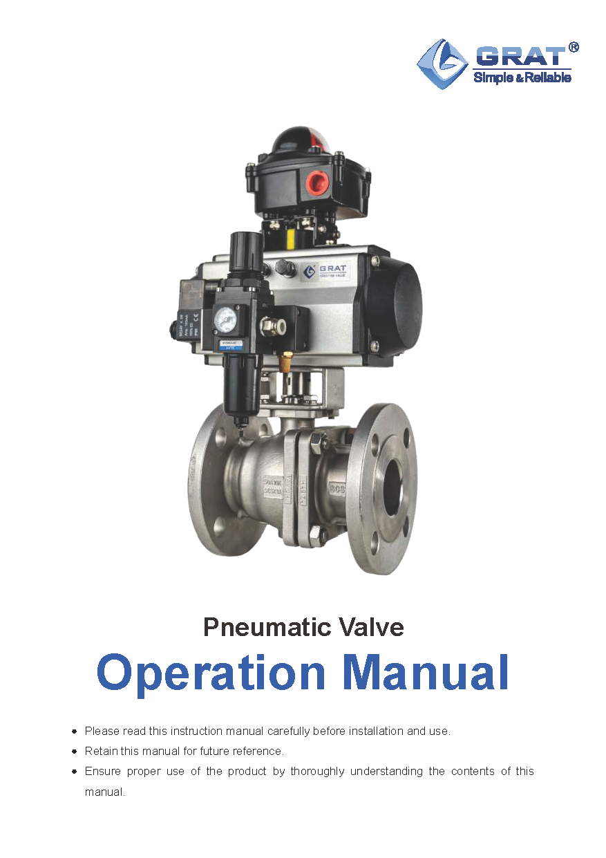
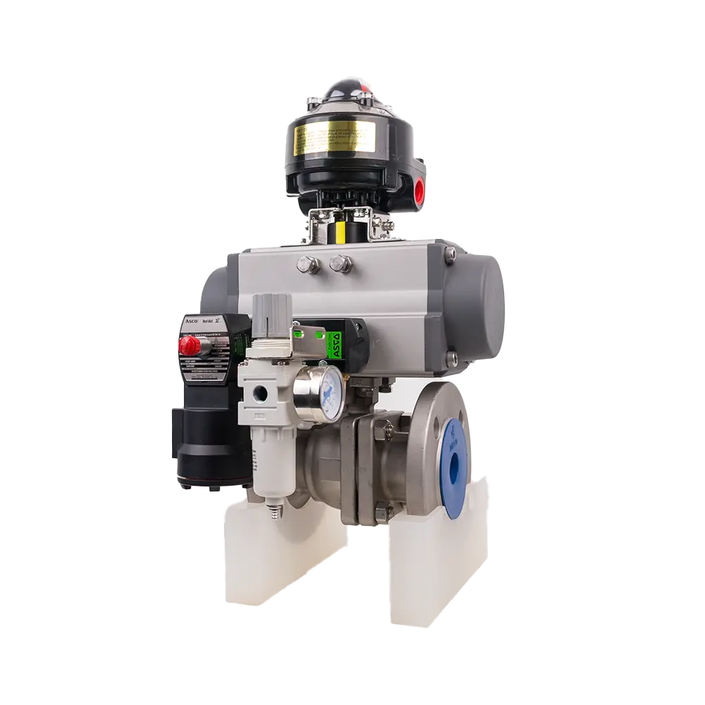
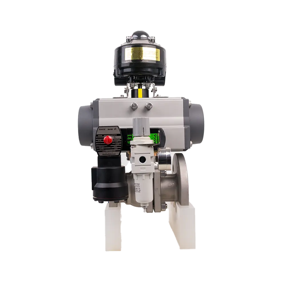
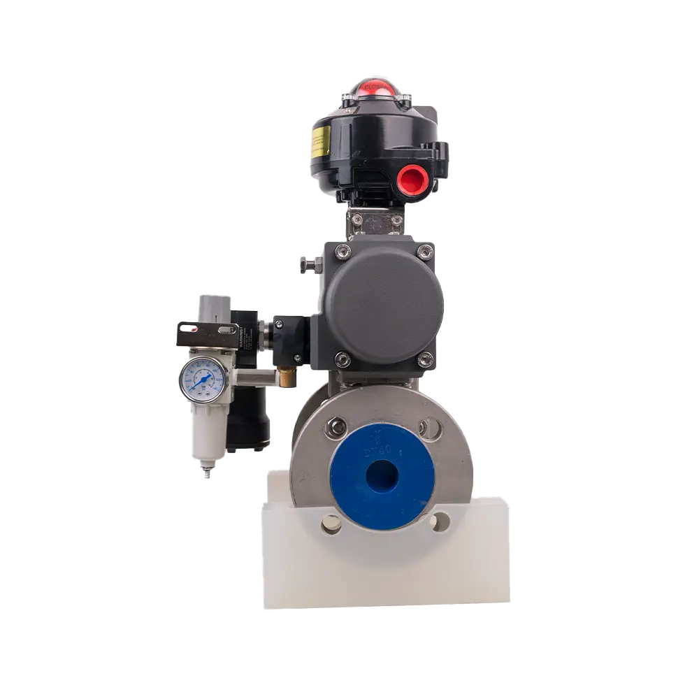
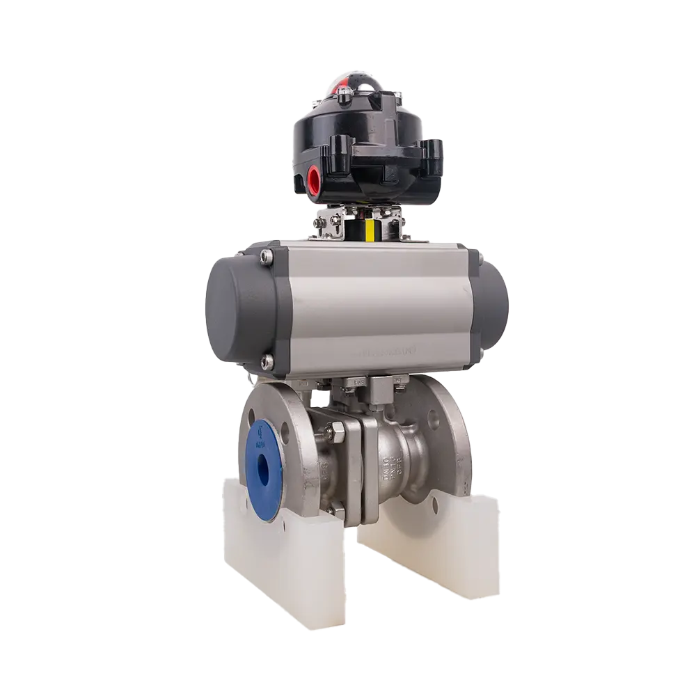
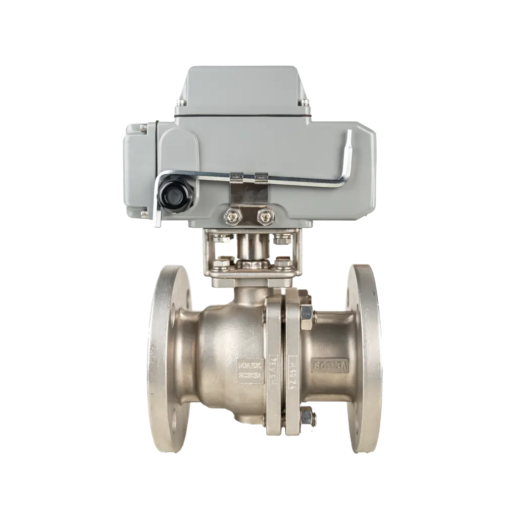

Pneumatic Flange Ball Valve
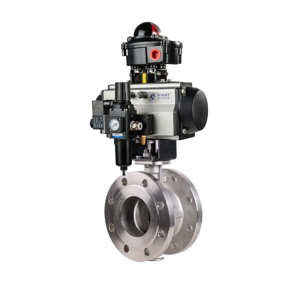
Pneumatic flanged ball valves are driven by a pneumatic actuator to rotate the ball 0–90° for opening and closing. They feature reliable sealing and low flow resistance, are compatible with various media, and are widely used in industrial control fields such as petrochemical and metallurgical industries.
Tags
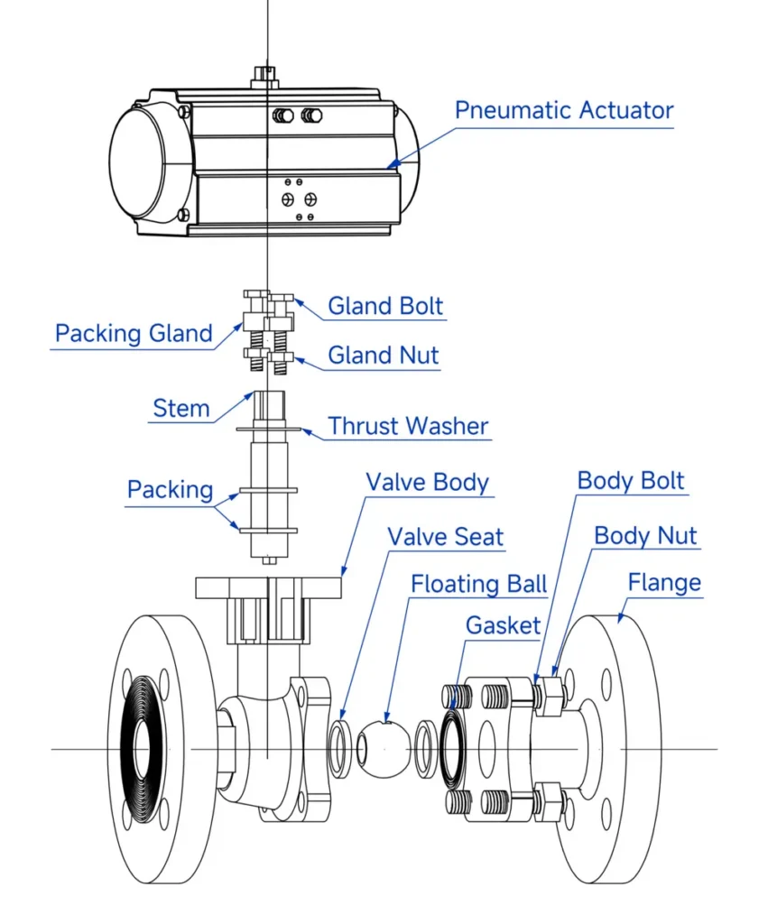
Features
- Ultra-reliable sealing: Adopts double-sided spherical sealing structure, with sealing performance reaching zero-leakage standard to ensure no leakage during medium transportation;
- Excellent wear resistance and durability: Specially designed PTFE seal features outstanding self-lubrication, low friction loss with the ball, and significantly extends service life;
- Flexible working condition adaptability: The ball core passage is available in rectangular, V-shaped and O-shaped options, which can be flexibly adapted to different flow control requirements.
Basic Parameters
Nominal Diameter (DN):
DN15 - DN200
Operating Power Supply:
AC110V, AC220V, AC380V, DC24V
Medium Temperature:
-20°C to 350°C
(Special sealing for >200°C)
Working Pressure:
PN1.0 ~ 10.0MPa
Control Method:
Modulating or On/Off Control
Protection Class:
IP67
Connection & Sealing
Connection Type:
Flange Type
Sealing Type:
Elastic Seal, High-Temperature Resistant PPS (Polyphenylene Sulfide), Hard Alloy & Industrial Ceramics
Leakage Rate:
Complies with ANSI B16.104 Class 5 Standard
Material Specifications
Body & Internal Components
Body Material:
A105, F304, F316, WCB, FZG1Cr18Ni9Ti, ZG1Cr18Ni12Mo2Ti, CF8, CF8M, CF3M
Ball Material:
SUS304, SUS316
Sealing Components
Seat Material:
PTFE (Normal Temperature)
Special PPL (High Temperature)
Metal Seal (High Temperature)
Applicable Medium
- Water
- Petroleum
- Nitric Acid
- Acetic Acid
- Viscous Fluids
- Slurries
- Strong Oxidizing Media
Standards Compliance
Design & Manufacturing:
GB 12237-2007, API 6D
Flange Standards:
- JB/T 79-2015
- GB/T 9124.1-2019
- GB/T 9124.2-2019
- ANSI B16.5
- JIS B2239
Face-to-Face Dimension:
GB 12221-2005
Inspection Standard:
API 598
Main Parameters
| Power Supply | AC110V, AC220V, AC380V, DC24V |
| Nominal Diameter | DN15-200 |
| Medium Temperature | -20℃ to +350℃ (+200℃ for special seal) |
| Working Pressure | PN1.0~10.0MPa |
| Control Mode | Regulation or On-Off Control |
| Pneumatic Actuation | Single-acting (with spring return) or Double-acting |
| Connection Type | Flanged |
| Body Material | A105, F304, F316, WCB, FZG1Cr18Ni9Ti, ZG1Cr18Ni12Mo2Ti, CF8, CF8M, CF3M |
| Seat Material | PTFE (normal temperature), Special PPL (high temperature), Metal seal (high temperature) |
| Leakage Class | ANSI B16.104 Class 5 |
| Sealing Type | Elastic seal, High temperature resistant polyphenylene, Hard alloy, Industrial ceramic |
| Applicable Medium | Water, Petroleum, Nitric acid, Acetic acid, Viscous fluid, Slurry, Strong oxidizing medium |
| Protection Grade | IP67 |
| Design and Manufacturing Standard | GB12237-2021, API 6D |
| Flange Standard | JB/T 79-2015, GB/T 9124.1-2019, GB/T 9124.2-2019, ANSI B16.5, JIS B2239 |
| Face-to-Face Dimension | GB12221-2005 |
| Inspection Standard | API 598 |
Dimension Drawing
1.Installation Dimension Drawing of Pneumatic Flanged Ball Valve (Standard)
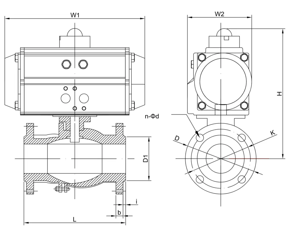
| Nominal Diameter (DN)) | L | D | K | D1 | n-Φd | b | i | Double Acting | Single Acting | |||||
| H | W1 | W2 | H | W1 | W2 | |||||||||
| mm | in | |||||||||||||
| 15 | 1/2″ | 130 | 95 | 65 | 45 | 4-Φ14 | 14 | 2 | 195 | 147 | 72 | 195 | 147 | 72 |
| 20 | 3/4″ | 130 | 105 | 75 | 55 | 4-Φ14 | 16 | 2 | 197 | 147 | 72 | 213 | 168 | 83 |
| 25 | 1″ | 142 | 113 | 85 | 65 | 4-Φ14 | 18 | 2 | 221 | 168 | 83 | 233 | 184 | 95 |
| 32 | 1 1/4″ | 165 | 140 | 100 | 78 | 4-Φ18 | 18 | 2 | 235 | 168 | 83 | 256 | 204 | 103 |
| 40 | 1 1/2″ | 165 | 150 | 110 | 85 | 4-Φ18 | 18 | 2 | 248 | 184 | 95 | 265 | 262 | 109 |
| 50 | 2″ | 203 | 165 | 125 | 100 | 4-Φ18 | 20 | 2 | 271 | 204 | 103 | 295 | 268 | 122 |
| 65 | 2 1/2″ | 222 | 185 | 145 | 120 | 8-Φ18 | 20 | 2 | 325 | 262 | 109 | 383 | 301 | 142 |
| 80 | 3″ | 241 | 200 | 160 | 135 | 8-Φ18 | 21 | 2 | 345 | 268 | 122 | 404 | 390 | 152 |
| 100 | 4″ | 305 | 220 | 180 | 155 | 8-Φ18 | 22 | 2 | 406 | 301 | 142 | 448 | 458 | 174 |
| 125 | 5″ | 356 | 250 | 210 | 184 | 8-Φ18 | 22 | 3 | 459 | 301 | 142 | 501 | 458 | 174 |
| 150 | 6″ | 394 | 285 | 240 | 210 | 8-Φ23 | 24 | 3 | 486 | 390 | 152 | 544 | 525 | 206 |
| 200 | 8″ | 457 | 340 | 295 | 265 | 12-Φ23 | 26 | 3 | 576 | 458 | 174 | 634 | 532 | 226 |
Note: The suitable actuator model may vary for pneumatic valves depending on the service medium, valve torque and control method, resulting in corresponding changes to relevant dimensions.
Circuit Diagram
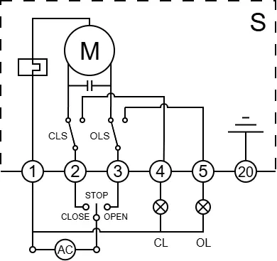
S
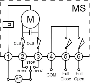
MS
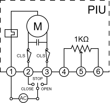
PIU
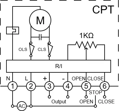
CPT
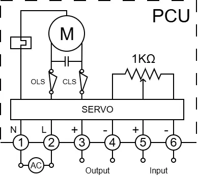
PCU
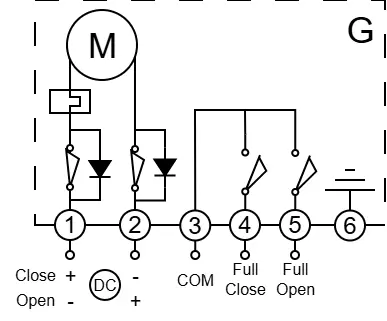
G
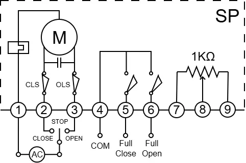
SP
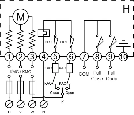
H
Circuit Diagram
S
MS
PIU
CPT
PCU
G
SP