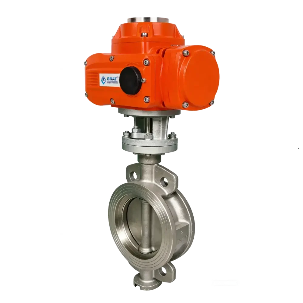
Electric PTFE-Lined Butterfly Valve
The electric PTFE-lined butterfly valve has a PTFE lining, which provides strong corrosion resistance and can handle various corrosive media. It is electrically driven, enabling precise control and being adaptable to automated systems.

Features
- FEP-lined, with all wetted parts in contact with liquid made of fluoroplastic. It features excellent corrosion and wear resistance, suitable for acids, alkalis and other media at any concentration, making it an ideal choice for corrosion-resistant equipment.
- The unique lip-type elastic sealing pair design effectively extends service life.
- PTFE sealing material is aging-resistant, corrosion-resistant and durable, achieving zero leakage.
Basic Parameters
Operating Power:
AC110V, AC220V, AC380V, DC24V
Nominal Diameter (DN):
DN40~DN500
Medium Temperature:
-50℃~160℃ (Non-freezing)
Working Pressure (PN):
1.0~1.6 MPa
Control Method:
Modulating or On/Off Control
Pneumatic Action Mode:
- Single Acting (with spring return)
- Double Acting
Connection Type:
Wafer Type
Material Specifications
Body & Internal Components
Valve Body Material:
WCB, QT450-10, HT200, HT250
Valve Disc Material:
WCB + PTFE
Seal Ring Material:
PTFE
Actuator Material:
Cast Aluminum Alloy
Suitable Media
- Sulfuric acid
- hydrofluoric acid
- phosphoric acid
- chlorine gas
- strong alkali
- aqua regia
- any other highly corrosive media
Standards Compliance
Design & Manufacturing:
GB/T 12238-2008, API 6D
Flange:
- JB/T 79-2015
- GB/T 9124.1-2019
- GB/T 9124.2-2019
- ASME B16.5
- JIS B2239
Structure Length:
GB/T 12221-2005
Inspection:
API 598
Main Parameters
| Power Supply | AC110V, AC220V, AC380V, DC24V |
| Nominal Diameter | DN40–DN500 |
| Medium Temperature | -50℃ – 160℃ (non-freezing) |
| Working Pressure | PN1.0~1.6 MPa |
| Control Mode | Modulating or On-Off control |
| Connection Type | Wafer Type |
| Body Material | WCB, QT450-10, HT200, HT250 |
| Disc Material | WCB + PTFE |
| Seal Ring | PTFE |
| Actuator Material | Cast Aluminum Alloy |
| Suitable Media | Sulfuric acid, hydrofluoric acid, phosphoric acid, chlorine gas, strong alkali, aqua regia, and any other highly corrosive media |
| Design & Manufacturing Standard | GB/T 12238-2008, API 6D |
| Flange Standard | JB/T 79-2015, GB/T 9124.1-2019, GB/T 9124.2-2019, ASME B16.5, JIS B2239 |
| Face-to-Face Dimension | GB/T 12221-2005 |
| Inspection Standard | API 598 |
Dimension Drawing
1.Wafer Type Electric PTFE Lined Butterfly Valve

| Nominal Diameter (DN) | L | D | N-ΦD | H1 | H2 | W1 | W2 |
| 40 | 33 | 115 | 4-Φ16 | 260 | 60 | 196 | 145 |
| 50 | 43 | 125 | 4-Φ18 | 270 | 70 | 196 | 145 |
| 65 | 46 | 145 | 4-Φ18 | 283 | 80 | 196 | 145 |
| 80 | 46 | 160 | 8-Φ18 | 327 | 89 | 255 | 182 |
| 100 | 52 | 180 | 8-Φ18 | 334 | 105.5 | 255 | 182 |
| 125 | 56 | 210 | 8-Φ18 | 357 | 121 | 255 | 182 |
| 150 | 56 | 240 | 8-Φ22 | 372 | 145 | 255 | 182 |
| 200 | 60 | 295 | 12-Φ22 | 420 | 177 | 255 | 182 |
| 250 | 66 | 355 | 12-Φ26 | 518 | 205 | 354 | 273 |
| 300 | 78 | 410 | 12-Φ26 | 535 | 235 | 354 | 273 |
| 350 | 78 | 470 | 16-Φ26 | 581 | 260 | 354 | 273 |
| 400 | 102 | 525 | 16-Φ30 | 630 | 299 | 354 | 273 |
| 450 | 114 | 585 | 20-Φ30 | 682 | 320 | 354 | 273 |
| 500 | 127 | 650 | 20-Φ33 | 710 | 352.5 | 354 | 273 |
Circuit Diagram

S

MS

PIU

CPT

PCU

G

SP