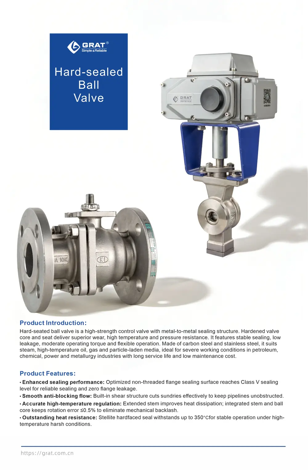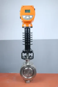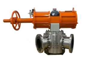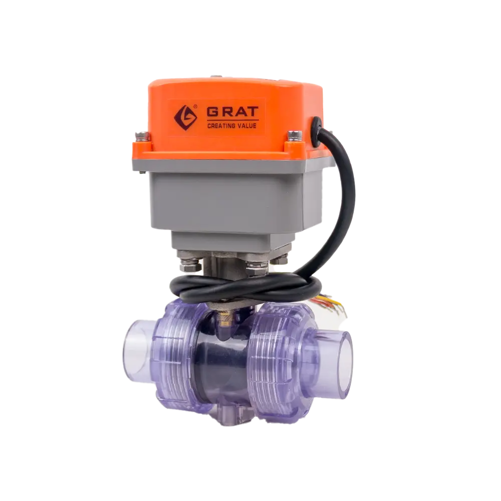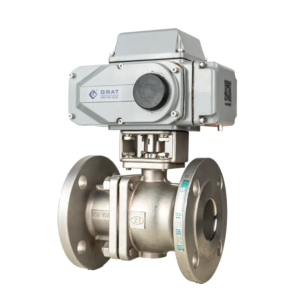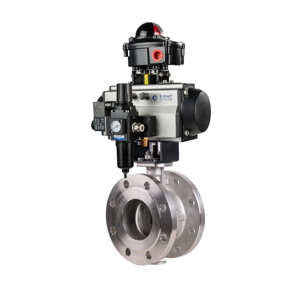
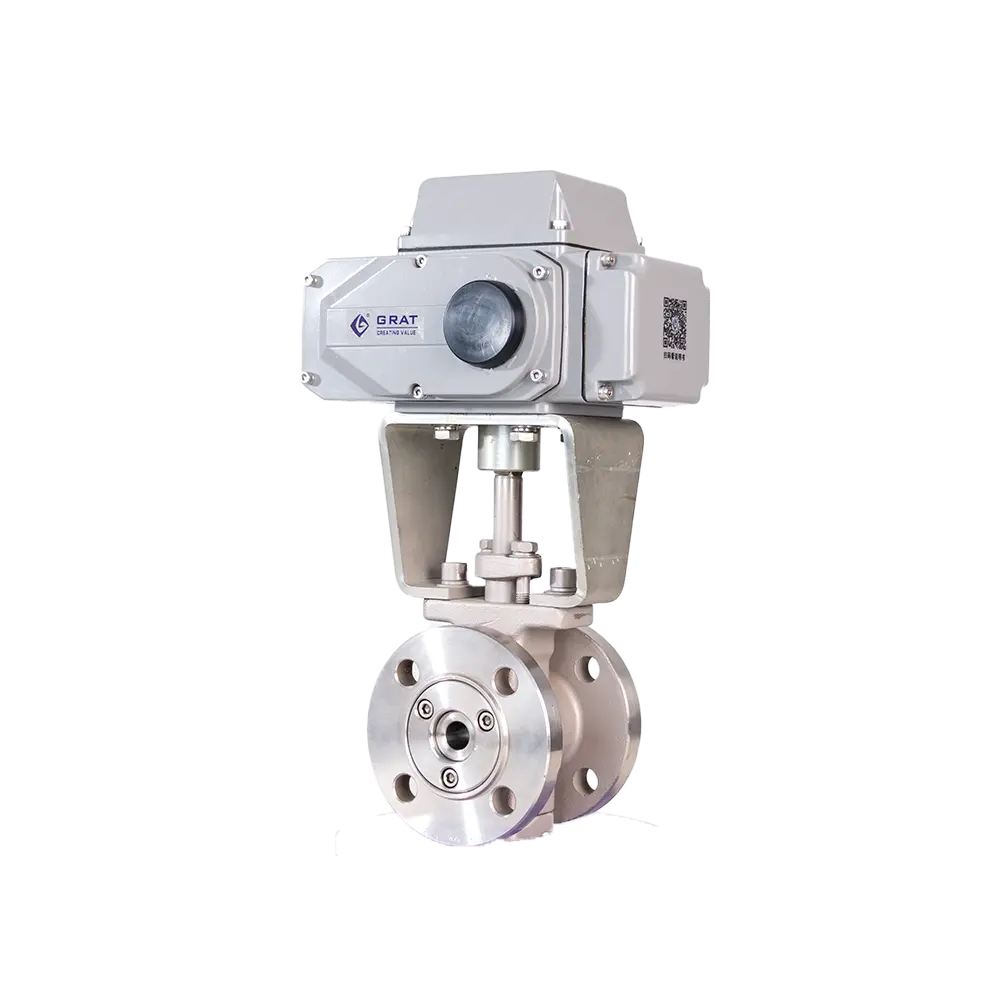
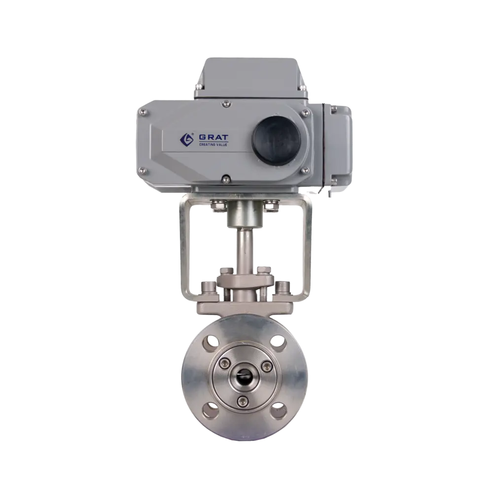
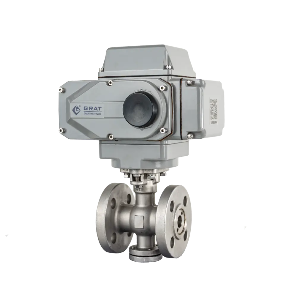
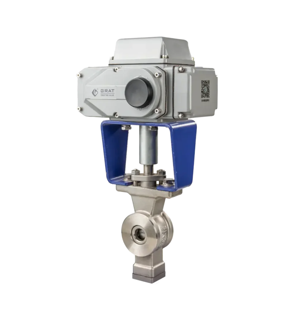

Electric Hard-Sealed Ball Valve
Hard-faced metal seats deliver wear and high-temperature resistance. Electric-actuated for fast cycling, built for on/off and throttling duty under harsh operating conditions.
Tags
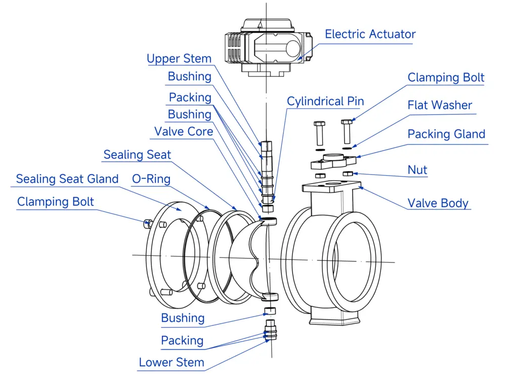
Features
- Isolation and control — cuts off or connects line fluid and supports modulating service; a pressure-retaining component for industrial process automation.
- Trunnion-mounted ball with floating seats — the ball is fixed and will not shift under pressure; line pressure drives the floating seat onto the ball to hold a tight seal.
- Fast, simple operation — a 90° turn runs full open to full closed; readily adapted to remote control.
- Full-bore, straight-through flow path — low pressure drop, non-binding, erosion-resistant.
- Maintenance-free — no routine servicing required in operation, lowering upkeep cost.
Basic Parameters
Nominal Diameter (DN):
DN15-DN350
(For larger diameters, please contact our company for detailed information)
Nominal Pressure:
PN1.6~6.4MPa
Operating Power Supply:
AC110V, AC220V, AC380V, DC24V
Medium Temperature:
≤450℃
Ambient Temperature:
-30~60℃
Control Method:
Modulating or On/Off Control
Actuation Time:
15~120 seconds (0-90°) optional
Dead Band:
0.3%~3.0% adjustable
Connection & Sealing
Connection Type:
Wafer Connection, Flange Connection
Seat Type:
Stainless Steel Movable Hard Seal
Material Specifications
Body & Internal Components
Body Material:
WCB, SS304, SS316, SS316L
Seat Material:
SS304, SS316, SS316L
Valve Core Material:
SS304, SS316, SS316L
Applicable Medium
- Mineral Slurry
- Coal Slurry
- Paper Slurry
- Water
- Oil
- Gas
Standards Compliance
Design & Manufacturing:
GB/T 12237-2007
Flange Standards:
- GB/T 9124.1-2019
- GB/T 9124.2-2019
- GB17241.6-2008
Face-to-Face Dimension:
GB12221-2005
Inspection Standard:
GB/T 13927-2008
Main Parameters
| Nominal Diameter | DN15–DN350 (For larger sizes, please contact our company for detailed data) |
| Nominal Pressure | PN1.6~6.4MPa |
| Connection Type | Wafer connection, Flange connection |
| Seat Type | Stainless Steel Movable Hard Seal |
| Operating Time | 15~120s (0–90°) adjustable |
| Power Supply | AC110V, AC220V, AC380V, DC24V |
| Control Mode | Modulating or On-Off control |
| Medium Temperature | ≤450℃ |
| Ambient Temperature | -30~60℃ |
| Suitable Media | Ore slurry, coal slurry, paper pulp, water, oil, gas |
| Dead Band | 0.3%~3.0% adjustable |
| Body Material | WCB, SS304, SS316, SS316L |
| Seat Material | SS304, SS316, SS316L |
| Ball/Plug Material | SS304, SS316, SS316L |
| Manufacturing Standard | GB/T 12237-2021 |
| Flange Standard | GB/T 9124.1-2019, GB/T 9124.2-2019, GB17241.6-2008 |
| Face-to-Face Standard | GB12221-2005 |
| Inspection Standard | GB/T 13927-2022 |
Installation Dimensions of Explosion-proof Electric Ball Valve
1.Main Connection Dimensions of Electric Hard-Sealed Ball Valve (Wafer Type)
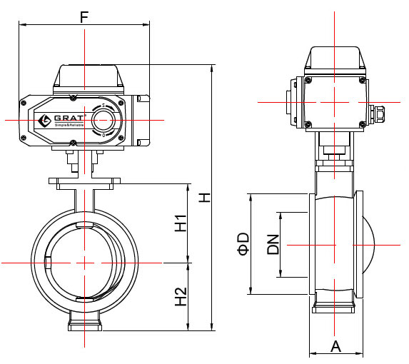
| Nominal DiameterDN(mm) | in | A | φD | H1 | H2 | H | W1 | W2 |
| 15 | 1/2" | 62 | 54 | 74 | 75 | 390 | 196 | 145 |
| 20 | 3/4" | 62 | 54 | 74 | 75 | 390 | 196 | 145 |
| 25 | 1" | 62 | 54 | 74 | 75 | 390 | 196 | 145 |
| 32 | 1 1/4" | 62 | 78 | 80 | 75 | 400 | 196 | 145 |
| 40 | 1 1/2" | 62 | 82 | 85 | 75 | 405 | 196 | 145 |
| 50 | 2" | 75 | 100 | 87 | 95 | 430 | 196 | 145 |
| 65 | 2 1/2" | 80 | 120 | 105 | 115 | 498 | 255 | 182 |
| 80 | 3" | 100 | 131 | 115 | 125 | 520 | 255 | 182 |
| 100 | 4" | 115 | 158 | 125 | 125 | 530 | 255 | 182 |
| 125 | 5" | 130 | 180 | 140 | 155 | 570 | 255 | 182 |
| 150 | 6" | 160 | 216 | 153 | 165 | 600 | 255 | 182 |
| 200 | 8" | 200 | 260 | 200 | 195 | 680 | 255 | 182 |
| 250 | 10" | 240 | 325 | 225 | 225 | 730 | 255 | 182 |
| Pressure Test:The shell hydrostatic test pressure is 1.5 times the maximum working pressure, and the seal test pressure is 1.1 times the maximum working pressure. Test Medium: Water | ||||||||
2.Main Connection Dimensions of Electric Hard-Sealed Ball Valve (Flanged Type)
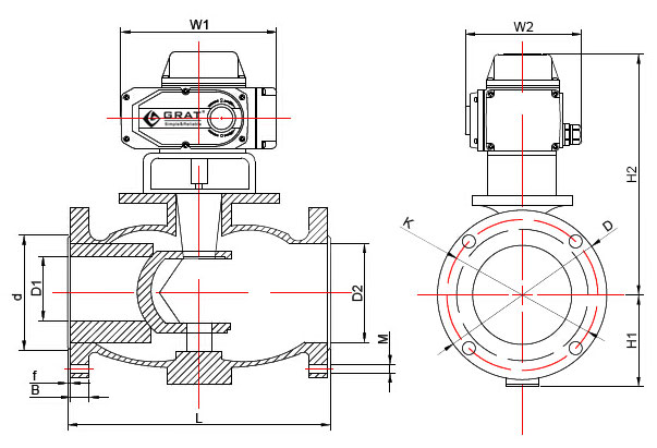
Design Standard: GB/T 12237-2007
Flange Standard: GB/T 9113-2010 National Standard Unit: (mm)
| DN (mm) | in | D1 | D2 | d | K | D | M | B | F | L | H1 | H2 | W1 | W2 |
| 15 | 1/2" | 15 | 28 | 45 | 65 | 95 | 4-Φ14 | 14 | 2 | 102 | 290 | 55 | 196 | 145 |
| 20 | 3/4" | 15 | 28 | 55 | 75 | 105 | 4-Φ14 | 14 | 2 | 102 | 300 | 60 | 196 | 145 |
| 25 | 1" | 20 | 40 | 66 | 85 | 115 | 4-Φ14 | 14 | 2 | 102 | 310 | 65 | 196 | 145 |
| 32 | 1 1/4" | 25 | 46 | 78 | 100 | 135 | 4-Φ18 | 16 | 2 | 114 | 320 | 75 | 196 | 145 |
| 40 | 1 1/2" | 32 | 54 | 85 | 110 | 145 | 4-Φ18 | 16 | 2 | 114 | 330 | 80 | 196 | 145 |
| 50 | 2" | 40 | 65 | 100 | 125 | 160 | 4-Φ18 | 16 | 2 | 124 | 340 | 85 | 196 | 145 |
| 65 | 2 1/2" | 50 | 80 | 120 | 145 | 180 | 4-Φ18 | 18 | 2 | 145 | 350 | 100 | 196 | 145 |
| 80 | 3" | 65 | 100 | 135 | 160 | 195 | 8-Φ18 | 20 | 2 | 165 | 360 | 105 | 196 | 145 |
| 100 | 4" | 80 | 110 | 155 | 180 | 215 | 8-Φ18 | 20 | 2 | 194 | 420 | 115 | 196 | 145 |
| 125 | 5" | 100 | 135 | 185 | 210 | 245 | 8-Φ18 | 22 | 3 | 210 | 430 | 130 | 255 | 184 |
| 150 | 6" | 125 | 165 | 210 | 240 | 280 | 8-Φ23 | 24 | 3 | 229 | 450 | 150 | 255 | 184 |
| 200 | 8" | 160 | 205 | 265 | 295 | 335 | 12-Φ23 | 26 | 3 | 243 | 480 | 175 | 255 | 184 |
| 250 | 10" | 210 | 260 | 320 | 355 | 405 | 12-Φ26 | 30 | 3 | 297 | 520 | 220 | 255 | 184 |
| 300 | 12" | 250 | 322 | 375 | 410 | 460 | 12-Φ26 | 30 | 3 | 340 | 600 | 250 | 255 | 184 |
| 350 | 14" | 300 | 365 | 435 | 470 | 520 | 16-Φ26 | 34 | 3 | 422 | 630 | 280 | 255 | 184 |
3.Maximum Allowable Leakage Rate
| DN(mm) | Metal Seat | Soft Seat |
| 15 | 1.1ml/min | 0.12ml/min |
| 20 | 1.5ml/min | 0.16ml/min |
| 25 | 2.0ml/min | 0.20ml/min |
| 32 | 2.4ml/min | 0.24ml/min |
| 40 | 3.0ml/min | 0.30ml/min |
| 50 | 3.8ml/min | 0.38ml/min |
| 65 | 5.2ml/min | 0.52ml/min |
| 80 | 6.2ml/min | 0.62ml/min |
| 100 | 7.6ml/min | 0.76ml/min |
| 125 | 9.6ml/min | 0.96ml/min |
| 150 | 12.0ml/min | 1.20ml/min |
| 200 | 15.4ml/min | 1.54ml/min |
| 250 | 19.2ml/min | 1.92ml/min |
4.Standard Construction Materials
| Part Name | Material |
|---|---|
| Valve Body | Carbon Steel ASTM A216 WCC |
| Valve Body Liner | High Chromium Steel ASTM A532 Grade III Type A |
| V‑Notch Ball | High Chromium Steel ASTM A532 Grade III Type A |
| Seal Ring | High Chromium Steel ASTM A532 Grade III Type A |
| Seal Retaining Ring | Carbon Steel ASTM A105 |
| Bearing Protective Sleeve | High Chromium Steel ASTM A532 Grade III Type A |
| Bearing | 440C 58 HRC |
| Drive Shaft | 17‑4PH Condition H1025 |
| Driven Shaft | 17‑4PH Condition H1025 |
| Pin | Carbon Steel, Zinc Plated |
| Gasket | Graphite with Stainless Steel Wire |
| Packing | PTFE with Carbon Filler |
| Stuffing Box Ring & Protective Sleeve | 316 SST |
| Bolt | SA‑193‑B7 |
| Nut | SA‑194‑2H |
| Retaining Ring Screw & Latch | 316 SST |
| Seal Ring Liner (Optional) | PSZ Ceramic |
| V‑Notch Ball (Optional) | PSZ Ceramic |
Applicable Standards for Hard-Sealed Electric Control Valve
| Manufacturing Standard | GB/T 12237-1989 |
| Flange Standard | GB 9113-2000, GB 17241.6-1998 |
| Face-to-Face Standard | GB 12221-1989 |
| Inspection Standard | GB/T 13927-1992 |
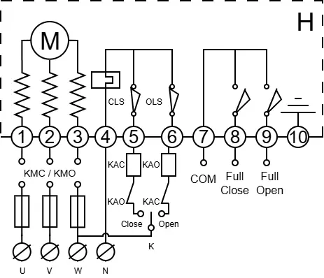
Circuit Diagram
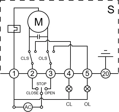
S
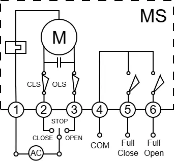
MS
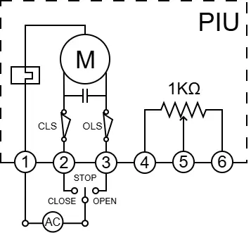
PIU
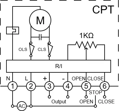
CPT
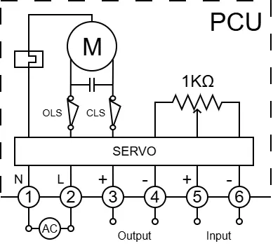
PCU
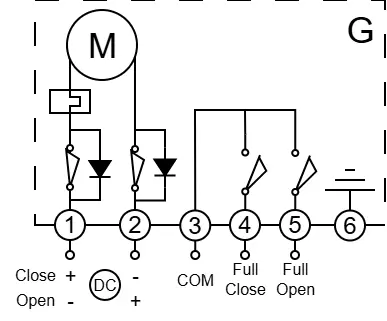
G
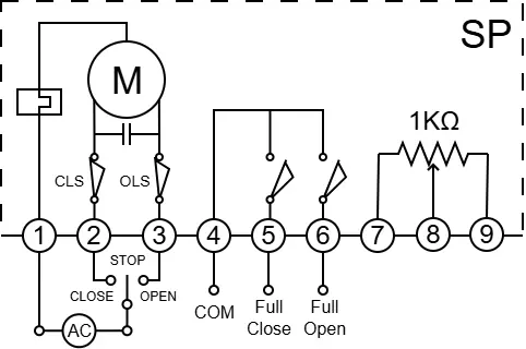
SP