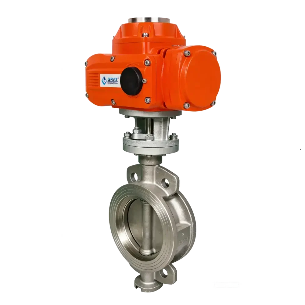
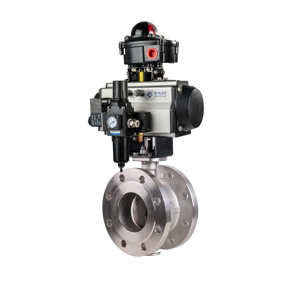
Explosion-Proof Electric Hard-Sealed Butterfly Valve
Explosion-proof hard-sealed butterfly valve adopts metal hard sealing structure, which is explosion-proof and suitable for hazardous chemical scenarios. It features fast opening and closing, excellent sealing performance, high resistance to high and low temperatures and corrosion, and is applicable to pipeline control of flammable and explosive media.

Features
- The valve stem is equipped with graphite-molded sealing rings to achieve zero leakage. It maintains full-time zero leakage under fire conditions and is classified as intrinsically fire-safe.
- The valve features low opening resistance. The sealing surface of the disc is designed as a convex cone, which disengages synchronously from the sealing ring upon opening.
- The sealing surface is not prone to solid accumulation, and sealing is achieved by the elasticity of the sealing ring during closing.
- There is nearly no friction between the valve seat and the disc, and the valve exhibits a tightening-sealing characteristic that becomes more reliable as it closes.
Basic Parameters
Nominal Diameter (DN):
DN15-DN350
(For larger diameters, please contact our company for detailed information)
Nominal Pressure (PN):
PN1.6~6.4MPa
Connection Mode:
Wafer type connection, Flange connection
Valve Seat Type:
Stainless steel movable hard seal
Action Time:
15~120 seconds (0-90°) optional
Working Power Supply:
AC110V, AC220V, AC380V, DC24V
Control Mode:
Regulating or on-off control
Pneumatic Action Mode:
Single acting (with spring return) or double acting
Medium Temperature:
≤450℃
Ambient Temperature:
-30~60℃
Dead Band:
0.3%~3.0% adjustable
Material Specifications
Body & Internal Components
Valve Body Material:
WCB, SS304, SS316, SS316L
Valve Seat Material:
SS304, SS316, SS316L
Valve Core Material:
SS304, SS316, SS316L
Applicable Medium
- Slurry
- Coal Slurry
- Paper Pulp
- Water
- Oil Products
- Gas
Explosion Protection
Ex db ⅡC T6 Gb
Flameproof enclosure with increased safety
Explosion Protection
Flameproof (d) + Increased Safety (b)
Gas Group
ⅡC (Hydrogen, Acetylene)
Temperature Class
T6 (≤85°C)
Equipment Protection Level
Gb (Zone 1 & 2)
Standards Compliance
Manufacturing Standard:
GB/T 12237-2021
Flange Standard:
- GB/T 9124.1-2019
- GB/T 9124.2-2019
- GB17241.6-2008
Structure Length Standard:
GB12221-2005
Inspection Standard:
GB/T 13927-2022
Main Parameters
1.Main Technical Parameters and Indicators of Hard-sealed Electric Regulating Valve Body
| Nominal Diameter (DN) | DN15-DN350 (For larger diameters, please contact our company for detailed information) |
| Nominal Pressure (PN) | PN1.6~6.4MPa |
| Connection Mode | Wafer type connection, Flange connection |
| Valve Seat Type | Stainless steel movable hard seal |
| Action Time | 15~120 seconds (0-90°) optional |
| Working Power Supply | AC110V, AC220V, AC380V, DC24V |
| Control Mode | Regulating or on-off control |
| Pneumatic Action Mode | Single acting (with spring return) or double acting |
| Medium Temperature | ≤450℃ |
| Ambient Temperature | -30~60℃ |
| Applicable Medium | Slurry, coal slurry, paper pulp, water, oil products, gas |
| Dead Band | 0.3%~3.0% adjustable |
| Valve Body Material | WCB, SS304, SS316, SS316L |
| Valve Seat Material | SS304, SS316, SS316L |
| Valve Core Material | SS304, SS316, SS316L |
| Manufacturing Standard | GB/T 12237-2021 |
| Flange Standard | GB/T 9124.1-2019, GB/T 9124.2-2019, GB17241.6-2008 |
| Structure Length Standard | GB12221-2005 |
| Inspection Standard | GB/T 13927-2022 |
Dimension Drawing
1.Explosion-proof Flanged Hard-seal Butterfly Valve Dimension Drawing

| Nominal Diameter (DN) | L | D1 | D2 | 4-Φd | H1 | H2 | W1 | W2 |
| 50 | 43 | 125 | 105 | 18 | 267 | 112 | 217 | 150 |
| 65 | 46 | 145 | 125 | 18 | 284 | 115 | 217 | 150 |
| 80 | 56 | 160 | 140 | 18 | 289 | 120 | 217 | 150 |
| 100 | 64 | 180 | 160 | 18 | 347 | 138 | 268 | 180 |
| 125 | 70 | 210 | 190 | 18 | 352 | 164 | 268 | 180 |
| 150 | 71 | 240 | 215 | 22 | 381 | 175 | 268 | 180 |
| 200 | 76 | 295 | 270 | 22 | 399 | 208 | 268 | 180 |
| 250 | 83 | 355 | 325 | 26 | 449 | 243 | 268 | 180 |
| 300 | 92 | 410 | 375 | 26 | 529 | 283 | 268 | 180 |
| 350 | 102 | 470 | 435 | 26 | 559 | 310 | 268 | 180 |
| 400 | 114 | 525 | 545 | 30 | 570 | 340 | 354 | 273 |
| 450 | 127 | 585 | 565 | 30 | 600 | 380 | 354 | 273 |
| 500 | 154 | 650 | 590 | 33 | 680 | 410 | 354 | 273 |
| 600 | 165 | 770 | 690 | 36 | 750 | 470 | 354 | 273 |
| 700 | 190 | 840 | 805 | 36 | 810 | 550 | 354 | 273 |
| 800 | 203 | 950 | 915 | 39 | 905 | 640 | 354 | 273 |
| 900 | 216 | 1050 | 1015 | 39 | 960 | 710 | 354 | 273 |
| 1000 | 254 | 1170 | 1120 | 42 | 1010 | 770 | 354 | 273 |
| 1200 | 265 | 1390 | 1335 | 48 | 1175 | 890 | 354 | 273 |
2.Explosion-proof Hard-sealed Wafer Butterfly Valve Dimension Drawing

| Nominal Diameter (DN) | L | D1 | D2 | n-Φd | B | C | H1 | H2 | W1 | W2 |
| 50 | 108 | 125 | 165 | 4-Φ18 | 16 | 2 | 267 | 112 | 217 | 150 |
| 65 | 112 | 145 | 185 | 4-Φ18 | 16 | 2 | 284 | 115 | 217 | 150 |
| 80 | 114 | 160 | 200 | 8-Φ18 | 18 | 2 | 289 | 120 | 217 | 150 |
| 100 | 127 | 180 | 220 | 8-Φ18 | 20 | 3 | 347 | 138 | 252 | 163 |
| 125 | 140 | 210 | 250 | 8-Φ18 | 22 | 3 | 362 | 164 | 252 | 163 |
| 150 | 140 | 240 | 285 | 8-Φ22 | 24 | 3 | 381 | 175 | 252 | 163 |
| 200 | 152 | 295 | 340 | 12-Φ22 | 24 | 3 | 399 | 208 | 293 | 184 |
| 250 | 165 | 355 | 405 | 12-Φ26 | 26 | 3 | 449 | 243 | 293 | 184 |
| 300 | 178 | 410 | 460 | 16-Φ26 | 28 | 3.5 | 529 | 283 | 293 | 184 |
| 350 | 190 | 470 | 520 | 16-Φ30 | 30 | 3.5 | 559 | 310 | 293 | 184 |
| 400 | 216 | 525 | 580 | 20-Φ30 | 32 | 3.5 | 570 | 340 | 354 | 273 |
| 450 | 222 | 585 | 640 | 20-Φ33 | 40 | 3.5 | 600 | 380 | 354 | 273 |
| 500 | 229 | 650 | 715 | 20-Φ36 | 44 | 4 | 680 | 410 | 354 | 273 |
| 600 | 267 | 770 | 840 | 24-Φ36 | 54 | 4 | 750 | 470 | 354 | 273 |
| 700 | 292 | 840 | 910 | 24-Φ39 | 40 | 4 | 810 | 550 | 354 | 273 |
| 800 | 318 | 950 | 1025 | 28-Φ39 | 42 | 4 | 905 | 640 | 354 | 273 |
| 900 | 330 | 1050 | 1125 | 28-Φ42 | 44 | 5 | 960 | 710 | 354 | 273 |
| 1000 | 410 | 1170 | 1255 | 32-Φ48 | 46 | 5 | 1010 | 770 | 354 | 273 |
| 1200 | 470 | 1390 | 1485 | 32-Φ48 | 52 | 5 | 1175 | 890 | 354 | 273 |
Circuit Diagram

S

MS

PIU

CPT

PCU

G

SP