1 Core Principle
Pneumatic valves control fluid flow (air, gas, or liquids) using compressed air to actuate internal pistons or diaphragms. Unlike electric valves, they're explosion-proof, making them ideal for hazardous environments like chemical plants or oil refineries.
Key Advantage: No electrical sparks ,safer for volatile settings.

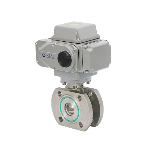
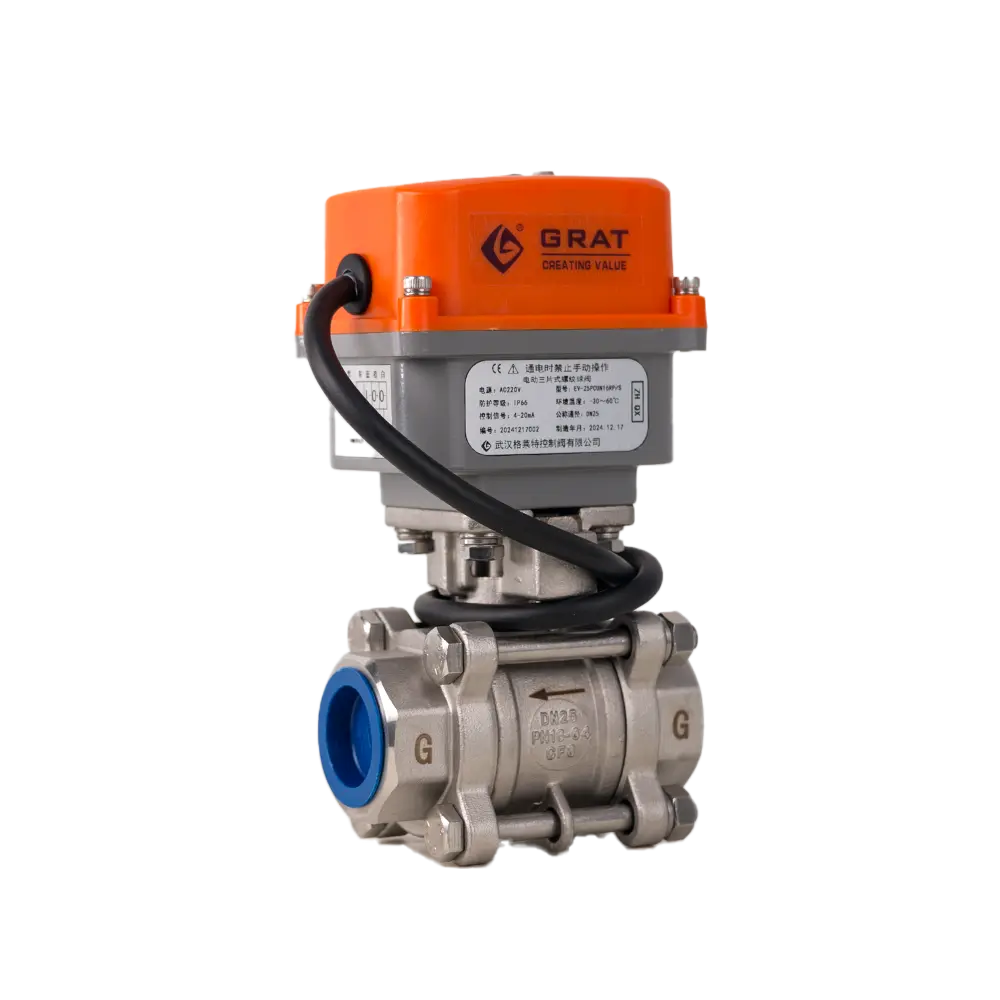
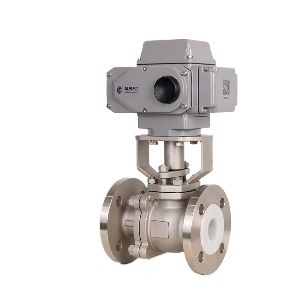
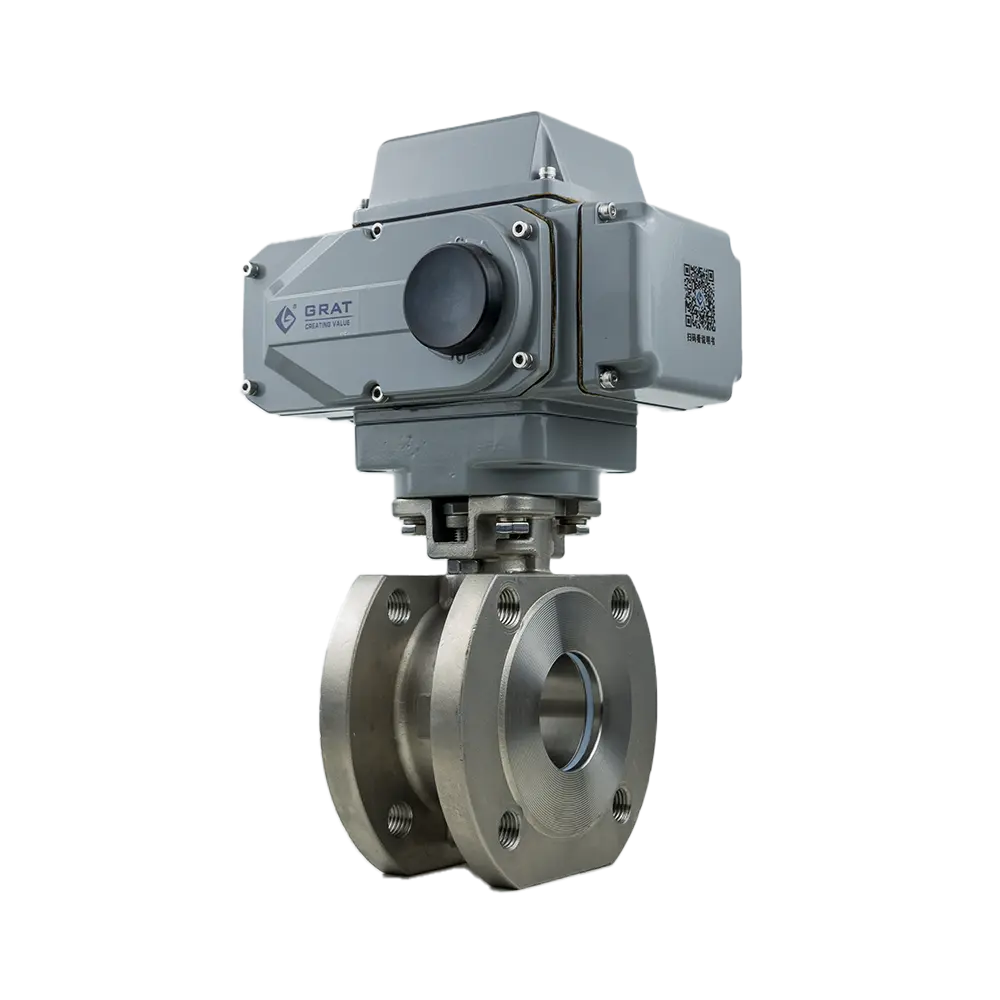
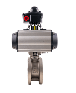
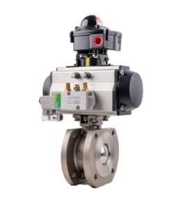
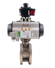
2 Key Components
Actuator: Converts air pressure into linear/rotary motion.
Valve Body: Contains ports and seals to direct flow.
Solenoid (for automated valves): Electrically controls air supply to the actuator.
Why It’s Reliable: Fewer moving parts, lower failure rates vs. hydraulic systems.
3 Compressed Air's Role
Air pressure (typically 20–120 psi) acts on the actuator’s piston/diaphragm. When pressure overcomes spring resistance, the valve shifts. Releasing pressure lets the spring return it to default.
Critical Factor: Air must be clean/dry to prevent corrosion or clogging.
4 Fail-Safe Mechanisms
Many pneumatic valves are "spring-return" – they auto-close if air supply fails (crucial for safety in power plants or chemical systems).
Alternative: Double-acting actuators (air moves valve both ways) for higher speed/force.
5 Speed & Precision
Response time is rapid (milliseconds), but flow control isn’t as precise as electric valves. For accuracy, proportional pneumatic valves modulate air pressure to adjust flow gradually.
Trade-off: Simplicity over precision; best for ON/OFF or coarse control.
6 Real-World Application
Example: In bottling plants, pneumatic valves control air bursts to clean bottles. Their durability and fast cycling outperform electric alternatives.
Takeaway: Pneumatic valves excel where speed, safety, and simplicity matter.